PE-505/508 Design Guide
Connectors and Pinouts
Ethernet Header (4 Pin)
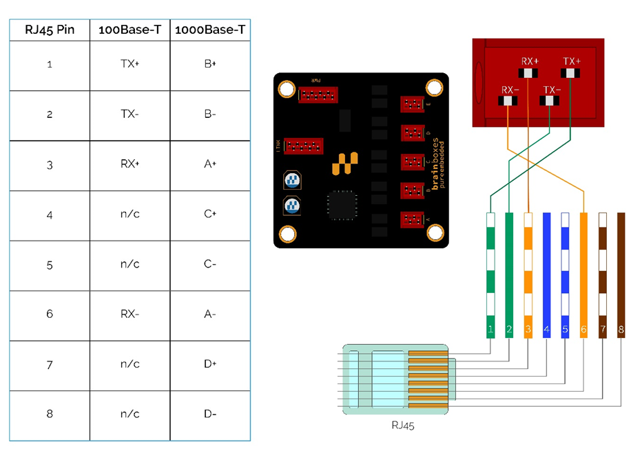
As the PE-505 and PE-508 supports Auto MDI/MDIX, the wiring of the RX and TX pins are reversible. See the Connectors section for the recommended pin configuration for the ethernet ports. Coloured Cat5 cable can be wired as shown.
For longer distances (>1.5 m), using shielded cable is optimal. Shielding can be attached to the Functional Earth mounting points on the bottom corners of the board.
Link LED Header (8 Pin)
Each of the ports have a Link Indicator LED and the first five have a Link Indicator Output. The output current must be limited through a resistor. The resistor must be selected to limit the maximum draw to 20 mA @ 3.3 V. The LEDs must be powered from the LED Power Pin. The LEDs function in an active LOW configuration and should be connected as shown below.
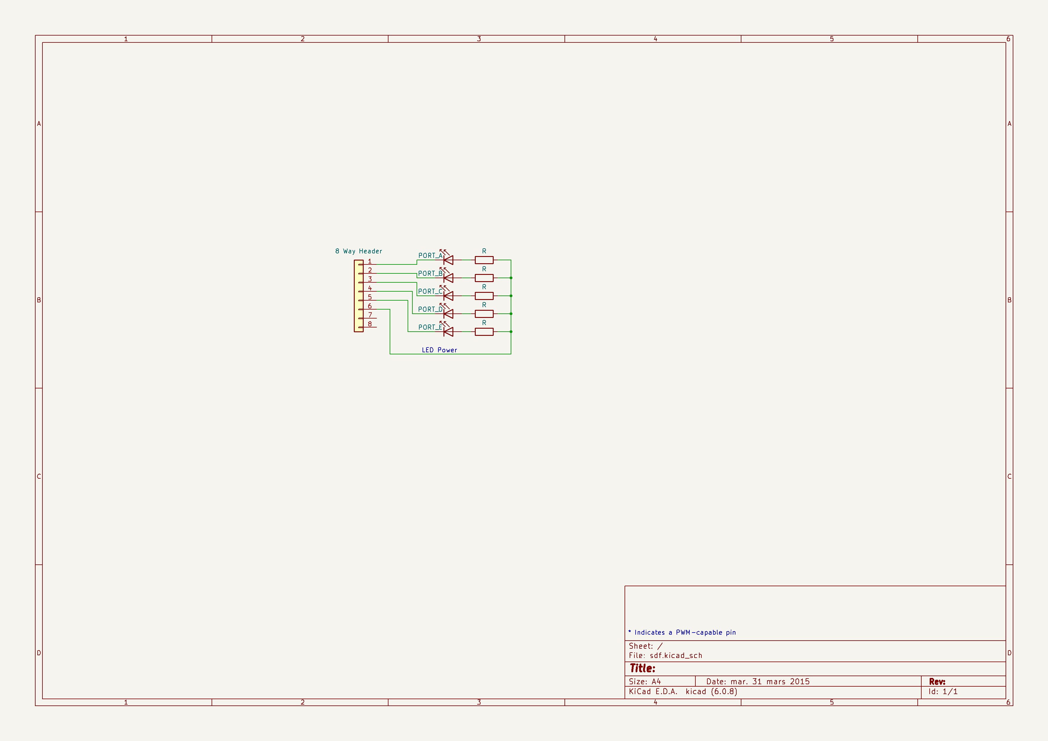
The power draw of any supplementary LEDs is in addition to the specified power on the datasheet. Should it be impractical to implement an electronic-based Link LED forwarding, there are holes of ⌀1 mm under the indication LEDs for ports A-E, suitable for housing optical fibres or light pipes of a length less than 50 cm.
Note: Not all LEDs are suitable for use with optical or copper cabling, please check specification prior to fitting.
Mounting Holes
The 4 x M3 mounting holes are connected to Functional Earth (FE) or Ground (GND) and labelled accordingly. If the device does not share a common ground with the rest of the system, it is recommended to use a nonconductive standoff or isolated mounting point.
2D Drawing

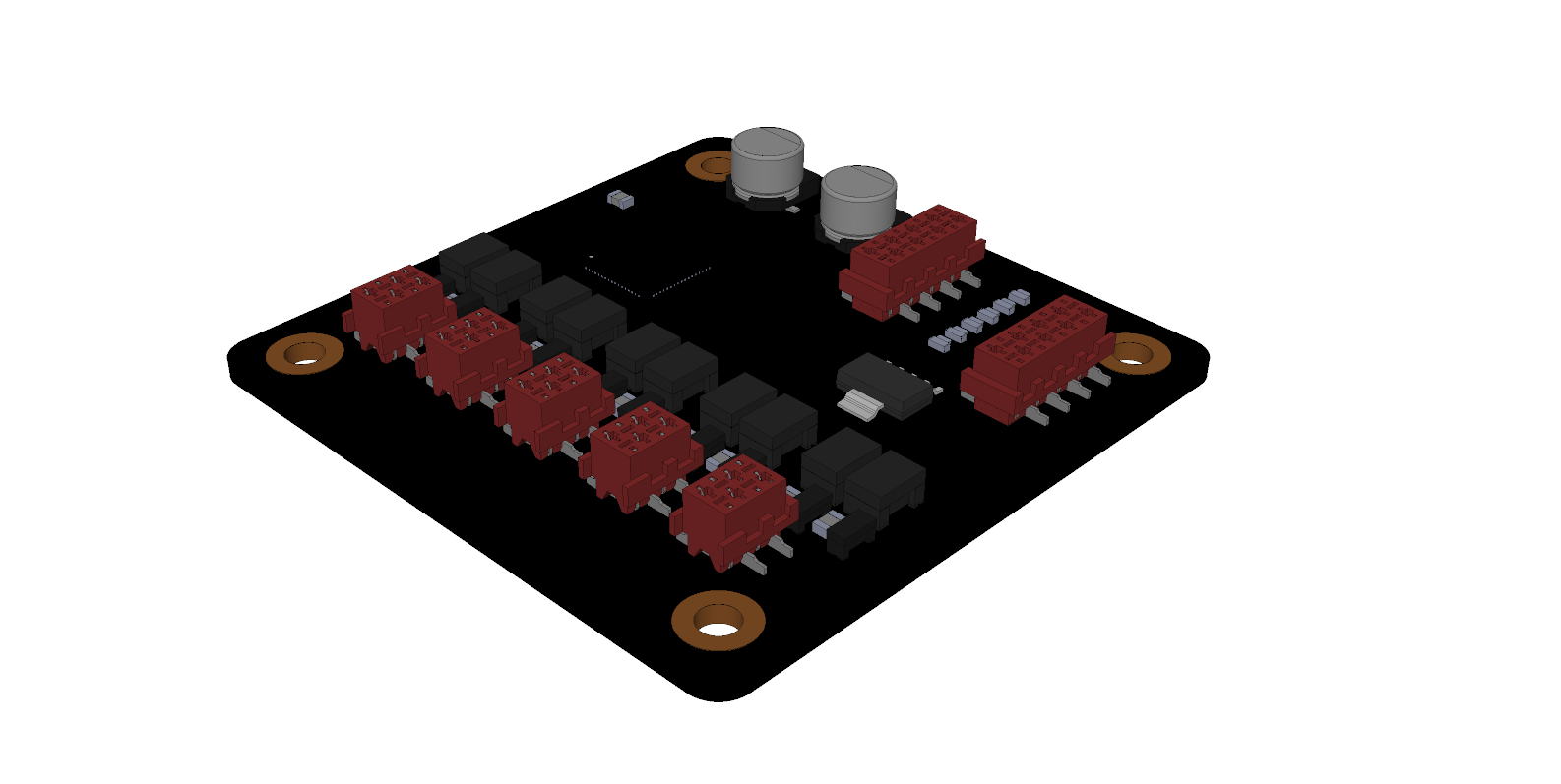
3D Step File
The full 3D model can be downloaded from the Brainboxes website:
Recommended Footprint
The mating LED Header and Port Header are not essential and can be excluded if not required. For applications where the module is frequently inserted and removed, we recommend using through-hole mating connectors. Avoid placing components within the 55 x 55 mm square occupied by the PE-505 or PE-508.
Recommended footprint can be downloaded from the Brainboxes website or constructed from the following:
- An array of 4-way headers with coordinates of: (4.5,6), (13.5,6), (22.5,6), (31.5,6), (40.5,6)
- 2 x 8-way headers with the centre locations: (2,35.5), (18,40)
- 4 x M3 mounting holes at: (0,0), (45,0), (0,45) and (45,45) (GND)
Either Through-Hole or SMT headers can be used as per the part numbers detailed in the Connectors section.
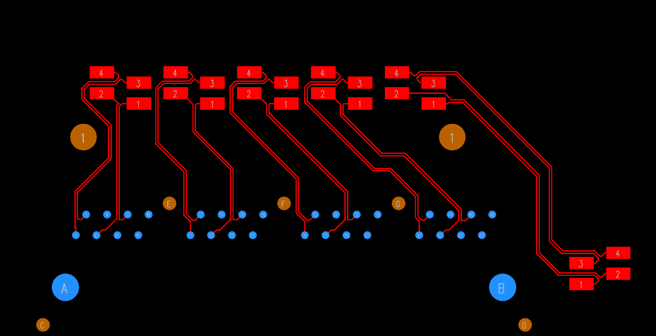
Routing
When designing custom boards for Brainboxes PE devices, it is important to take into consideration routing the device to connectors across a board.
Routing Recommendations
- Maintain uniform spacing between differential pairs to minimize signal degradation
- Keep pairs at as close length as possible
- Place a GND plane between different pairs
- Ensure pairs do not cross plane boundaries
For more information we recommend reading:
- Microchip AN2054 (Ethernet Differential Pairs)
- Texas Instruments SNLA387 (Ethernet PHY PCB Design Layout Checklist)