
ED Hardware Examples
This section provides practical wiring examples for connecting various hardware to your Brainboxes ED device.
Output to a Light Circuit
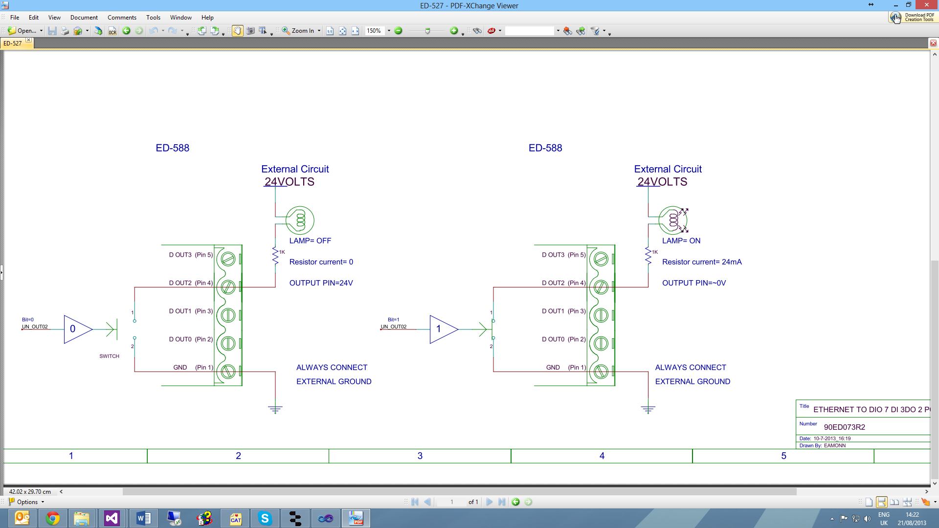
Basic example showing how to connect a light or LED to an ED output.
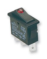
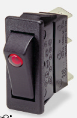
Switch Input Circuit
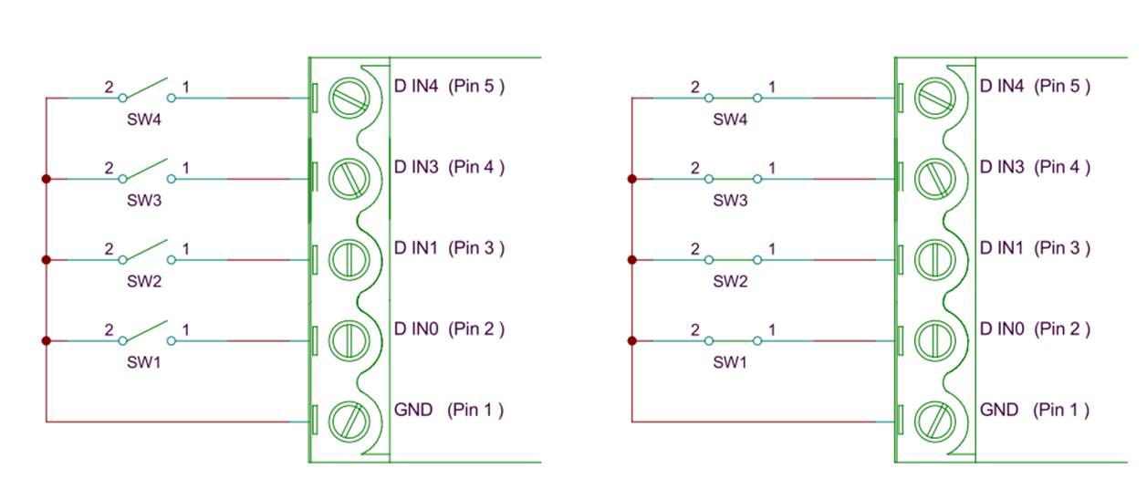
Example showing how to connect a simple switch to an ED input.
Digital Outputs: SINK

Specifications:
- Vss = 30V Max
These Sink Outputs act like a switch shorting the Digital Output to the GND pin. When the Output is off, the external circuit pulls up to its supply Voltage (Vss).
The ED-XXX outputs are current sinking outputs - they can easily pull the output down to ground but they cannot pull the output up.
Key Points:
- The +ve supply (Vss) to the load isn't related to the ED power supply voltage
- Ensure that the external circuit Ground is connected to the ED GND connection
- Maximum Current one ED port can sink is 1 Amp so large loads can be switched
- Vss = 30V Max
Digital Outputs: TTL Compatible
For TTL/5V CMOS Compatibility:
TTL outputs must drive below 0.35V for logic Low, and above 3.3V for logic High.
The ED outputs can drive down to below 0.35V while sinking over 1A, so the Low side of the output spec is not a problem.
ED Sink outputs do not drive high. To make the outputs TTL (or 5V CMOS) compatible, add a pull-up resistor (e.g., 10kΩ) from the outputs to 5V.
Ensure the external circuit Ground is connected to ED GND connection.
Turning ON Indicator Light
The ED-XXX outputs are current sinking outputs - they can easily pull the output down to ground but they cannot pull the output up.
When an LED and resistor is connected as shown, the LED lights when the Output is turned ON.
Example Configuration:
- 12V supply
- 20mA current
- 500 Ohm resistor
Logic Levels:
- 0V to 1V = "0"
Seven Segment Display Example
Example using RS part# 719-2522 (7 Segment Display):
- 12V supply
- Vf = 7.8V
- 20mA current
- 210 Ohm resistor
- 8 x 20mA = 160mA (still a small load even when all segments plus decimal point are lit)
Turning ON Indicator Sounds
When a Buzzer (e.g., RS Part# 754-2003) and resistor are connected, the Buzzer sounds when the Output is turned ON.
Logic Levels:
- 0V to 1V = "0"
Digital Inputs: NPN/PNP Compatible
ED-XXX Has 8 Digital Inputs. Each Input can be individually set to accept either NPN or PNP signals.
NPN/PNP Jumper Settings
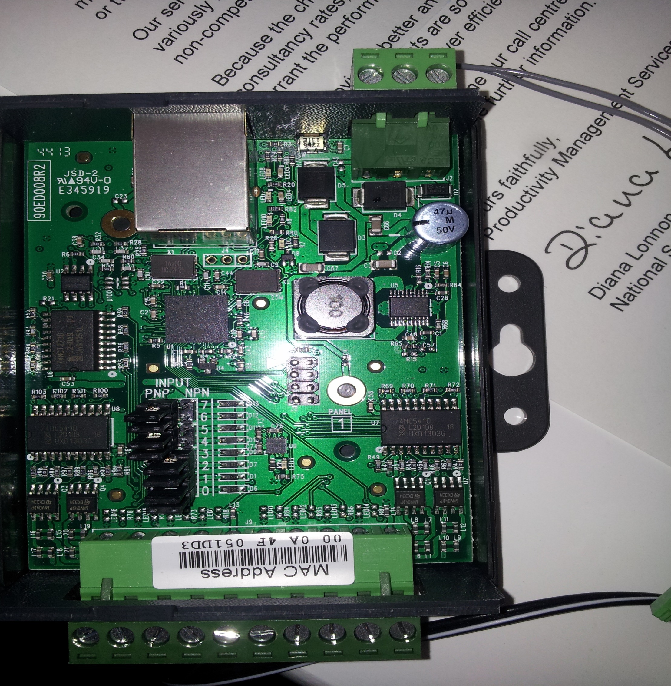
Jumper Positions:
- LEFT = PNP
- RIGHT = NPN (default)

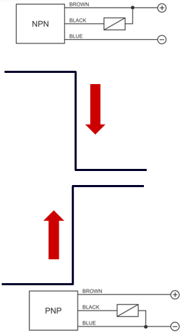
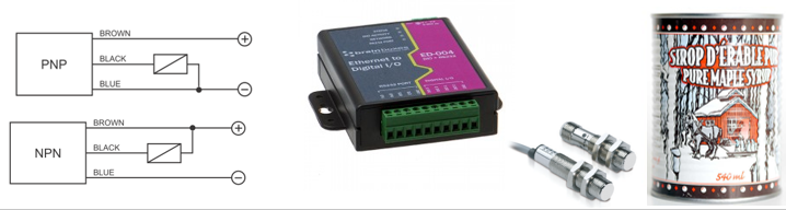
NPN vs PNP Sensors
NPN Sensor
| State | Output |
|---|---|
| Nothing near | Normally HIGH |
| Metal object near | Goes LOW |
PNP Sensor
| State | Output |
|---|---|
| Nothing near | Normally LOW |
| Metal object near | Goes HIGH |
Each sensor requires a Power Input of 12 Volts
Example Configuration:
- A PNP Sensor on DIO 5 = 020x
- A NPN Sensor on DIO 0 = 01x
Dry Contacts
A "Dry" contact is so called because it doesn't have any voltage on it. A switch is a typical dry contact.
:::question Problem If there is no voltage on it, how do I tell whether it's open or closed? :::
Example: Switch is DI 02 = Bit 4
Detecting Dry Contacts
Set the User Configurable PNP/NPN Jumper to NPN
Dry Contact / Volt Free Detection:
| State | Logic Level |
|---|---|
| Short to GND | 0 |
| Leave unconnected | 1 (inputs pull high) |

Dry Contact: PIR Detector
Inputs: A relay is a dry contact.
Example: PIR Alarm = DIO 1 = 02x
Sensors & Actuators
Sensors
![]()
Sensors connect to Inputs
A sensor is a mechanical device sensitive to light, temperature, radiation level, or the like, that transmits a signal to a measuring or control instrument.
Actuators
Actuators connect to Outputs
An actuator is a servomechanism that supplies and transmits a measured amount of energy for the operation of another mechanism or system.
What can I control?
Any device that can be switched on/off with a digital signal:
- Lights
- Motors (via relay/driver)
- Solenoids
- Valves
- Buzzers/Alarms
- Display elements