
UC Technical Specifications
Supported Serial Settings
| Serial Setting | Supported Values |
|---|---|
| Baud Rate | Up to 921,600 |
| Data Bits | 5, 6, 7 or 8 |
| Parity | None, Odd, Even, Mark & Space |
| Stop Bits | 1, 1.5 or 2 |
| Handshaking | RTS/CTS, DTR/DSR, Xon/Xoff |
| Break | Supported |
Device Pin-out
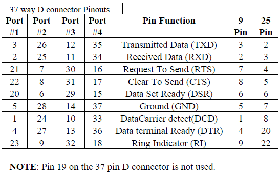
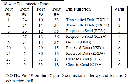
37 Way D Connector
RS-232 Pinout
RS-232 Card(s): UC-268
RS-422 Pinout
RS-422/485 Card(s): UC-346 and UC-368
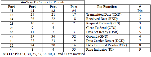
44 Way D Pin Connector
RS-232 Card(s): UC-263, UC-260, UC-701, UC-049, UC-061, UC-072, UC-083, UC-295, UC-253, UC-734
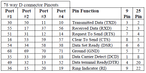
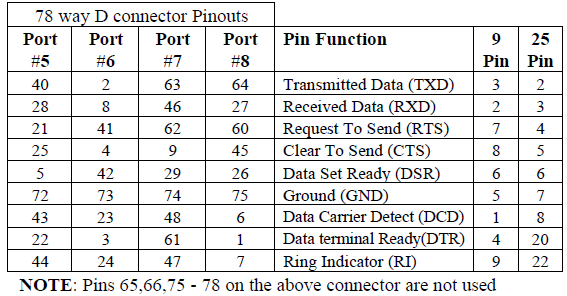
78 Way D Pin Connector
RS-232 Card(s): UC-279
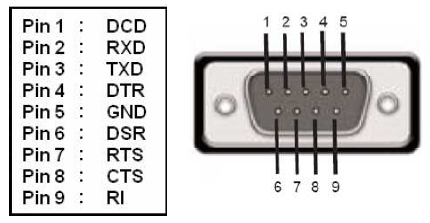
RS-232 Devices
Standard 9-pin D connector pinout for RS-232 devices.
RS-422/485 Devices
Standard 9-pin D connector pinout for RS-422/485 devices.
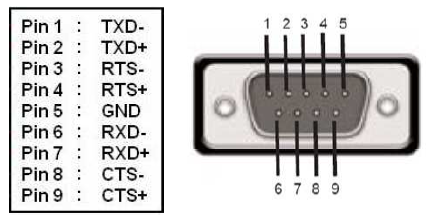
- DTR/DSR Handshaking is not available on RS-422/485 devices
- For RS-422 Full Duplex communications, please note outputs above
- To achieve RS-485 Half Duplex communications, using two wires for communication, Pins 1 and 6, 2 and 7 must be physically shorted
- Once your wiring is setup, you will also need to set the card to FULL or HALF Duplex mode in the software. For further details, see Product Configuration
Terminating Resistors
RS-422 and RS-485 lines should be terminated at the end of the main branch of the RECEIVER, in the cable's characteristic impedance. These terminating impedances stop echoes caused by the serial data being reflected back at the cable ends.
It is not necessary to terminate the transmitter end of the twisted pair.
The AT Dual Port RS-422/485, Opto Isolated AT Dual Port RS-422/485 and AT Velocity RS-422/485 cards have the correct 120 ohm (nominal) terminating resistors for the RXD twisted pair line and the CTS twisted pair line fitted on the RS-422/485 card for both the serial ports on the card.
There is no need to add any more at the PC end.
The terminating impedances shown in the wiring diagrams are automatically provided by the on-board resistors and do not have to be added by the user.
Storage and Operating Environment Guidelines
Storage
| Parameter | Range |
|---|---|
| Temperature | -10 C to +70 C |
| Humidity | 8% to 95% non-condensing |
Operational
| Parameter | Range |
|---|---|
| Temperature | 0 C to +70 C |
| Humidity | 20% to 75% non-condensing |