
SW PoE Quick Start Guide
SW PoE Ethernet Switch Quick Start Guide
This guide covers the Brainboxes PoE (Power over Ethernet) Ethernet Switch range.
PoE Specifications
| Parameter | Specification |
|---|---|
| PoE Standards Supported | IEEE 802.3af/at (PoE/PoE+) |
| PoE Power Budget | 60W Max @ +44VDC to +50VDC |
| 90W Max @ +50VDC to +57VDC | |
| Operating Temp Range | -40°C to +70°C |
Power Wiring
5-Pin Dual Redundant Power Input
Applies to: SW-125, SW-525, SW-725, SW-135, SW-535, SW-735, SW-195, SW-595.
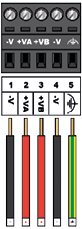
Dual redundant input is designated by +VA (pin 2) and +VB (pin 3):
- Wire +VA or +VB pins to positive (+ve) output of power source
- Wire -V pins (pins 1 & 4) to negative (-ve) output of power source
- Earth connection can be wired to Earth pin (pin 5)
| Parameter | Specification |
|---|---|
| Input Voltage Range (PoE) | +44VDC to +57VDC |
| Input Voltage Range (PoE+) | +50VDC to +57VDC |
| PSU Required | < 100W |
warning
Power source output voltage must be within PoE/PoE+ range: +44VDC to +57VDC. This equipment is not suitable for use in locations where children are likely to be present.
Port Diagrams
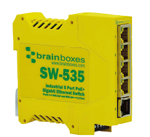
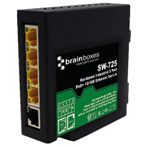
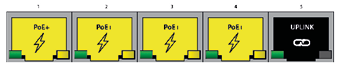
SW-X25 (Standard PoE Ports)
4 PoE ports + 1 uplink port.
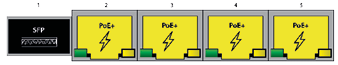
SW-X35 / SW-X95 (SFP + PoE Ports)
1 SFP port + 4 PoE+ ports.
LED Indicators
SW-X25
| LED | Colour | Meaning |
|---|---|---|
| Power LED | YELLOW | Power on |
| Link/Activity LED | GREEN | Link established |
| Link/Activity LED | FLASH | Data activity |
| PoE Power LED | FLASH | Power warning |
SW-X35 / SW-X95
| LED | Colour | Meaning |
|---|---|---|
| Power LED | GREEN | Power on |
| SFP LED | AMBER | SFP plugged in |
| SFP LED | AMBER FLASHING | SFP activity |
| SFP LED | GREEN/AMBER FLASHING | SFP error/incompatible |
| Link/Activity LED | GREEN | Link established |
| Link/Activity LED | FLASH | Data activity |
Recommended Power Supply
For DIN rail installations, use the PW-301 industrial power supply.