
VX RS-422/485 Settings
RS-422/485 Settings (VX-023 & VX-034 only)
To achieve RS-485 Half Duplex Communications, using two wires for communication, Pins 1 and 6 must be shorted together, and pins 2 and 7 must be physically shorted together.
Once your wiring is setup, you will also need to set the card to FULL or HALF Duplex mode in the software.
The RS-422 Standard
The RS-422 standard defines a serial communications standard. RS-422 is a high speed and/or long distance data transmission. Each signal is carried by a pair of wires and is thus a differential data transmission system. Over distances up to 40 feet the maximum data rate is 10 Megabits per second, and for distances up to 4000 feet the maximum data rate is 100 Kilobytes per second. A 120-Ohm resistor should be used to terminate the receiving end of the line. It is generally used between one transmitter receiver pair to ONLY one other transmitter receiver pair, but each output can drive up to 10 receivers.
| RS-422 Standard - 1 Driver up to 10 Receivers | |
|---|---|
| Line Length | Max Data Rate |
| 40 Feet = 12m | 10 Mbits/sec |
| 400 Feet = 122m | 1 Mbits/sec |
| 4000 Feet = 1219m | 100 Kbits/sec |

The RS-485 Standard
The RS-485 standard is similar to the RS-422 standard upon which it is based. The main difference is that up to 32 transmitter receiver pairs may be present on the line at one time. A 120-Ohm resistor should be used to terminate either end of the main line. If more than one device may transmit data, the RTS line is used as transmit enable signal, so preventing contention between talkers.
| RS-485 Standard - Up to 32 Driver/Receiver Pairs | |
|---|---|
| Line Length | Max Data Rate |
| 40 Feet = 12m | 10 Mbits/sec |
| 400 Feet = 122m | 1 Mbits/sec |
| 4000 Feet = 1219m | 100 Kbits/sec |

Terminating Impedances
RS-422 and RS-485 lines should be terminated at the end of the main branch of the RECEIVER, in the cables characteristic impedance. These terminating impedances stop echoes caused by the serial data being reflected back at the cable ends. It is not necessary to terminate the transmitter end of the twisted pair.
Brainboxes cards have the correct 120 Ohm (nominal) terminating resistors for the RXD twisted pair line and the CTS twisted pair line fitted on the RS-422/485 card for the serial ports on the card.
There is no need to add any more at the PC end.
The terminating impedances shown later in the wiring diagrams are automatically provided by the on board resistors and do not have to be added by the user.
This RS-422/485 termination circuit is based on the recommendation of Texas Instruments, and uses resistors to provide line termination Rt, bus-idle failsafing (biasing) Rb and bus-shorted failsafing, Rf.
However, this circuit may not be suitable for all RS-485 bus systems. Whilst the circuit includes line termination to prevent the data signal being reflected, this termination should only be present at each end of a bus and not at any intermediate nodes.
Also, while this circuit ensures that our US devices are properly biased when the bus is idle, this circuit may not provide sufficient bias for any nodes (i.e. external RS-485 devices) which have their receivers connected directly to the D+ and D- lines. If you do have RS-485 devices whose receivers are connected directly to the D+ and D- lines, you may need to add a couple of resistors to your bus, from D- to ground and from D+ to a positive supply, with a resistance sufficient to give at least 0.2V between D+ and D- when the bus is idle.
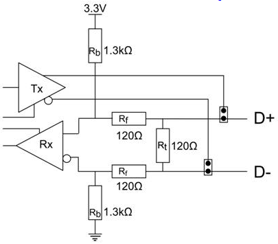
Fail Safe Open Circuit Detection
Open circuit is when there are no drivers on the circuit. This occurs by design in party line multi driver/receiver systems and unintentionally when the twisted pair line is accidentally cut or disconnected or the transmitting device fails. In RS-485 party line systems there are extended periods of time when none of the many possible talkers are gated onto the bus. This is known as the line idle state and occurs when all the driver outputs are in the high impedance state. The lines float, perhaps being pulled to the high or low state by noise or other voltages on the line. Without fail safe open circuit detection false start bits are detected by the receivers, either corrupting good communications or causing noise to masquerade as good data. The on board fail safe open circuit detection causes the receiver to go to a known, predetermined state and prevents false start bits and bad data being detected during open circuits.
Fail Safe Short Circuit Detection
Short circuits are when the two lines of a twisted pair are connected together. This occurs due to either accidental damage to the cable or due to failure of one or more transmitter/receivers on the line. The short circuit condition is dangerous since damage to the receiver may occur and communication may be corrupted or prevented. The on board fail safe short circuit detection prevents the line impedance from going to zero and thus protects the inputs of receivers and the outputs of drivers.
RS-422 Operation
Generally, in RS-422 systems all 8 signal lines from the 9 pin D connector participate in the data transfer sequence, thus 4 twisted pair cables are used. One twisted pair carries the TXD data outwards, one pair brings the RXD data inward, another pair carries the RTS handshake outwards and the fourth pair brings the CTS handshake inwards. There is no need to carry the ground from one device to another. This RS-422 arrangement allows data to be transmitted and received simultaneously since each signal has its own data cable pair. In addition, the receiver can set RTS true so telling the transmitter on its CTS input that the receiver is ready to accept data. In this way, no data will ever be transmitted when the receiver is unable to accept it, due to a full input buffer etc. And so no data will be lost.
RS-485 Operation
The RS-485 standard is intended for up to 32 driver receiver pairs on the bus. The line drivers used in the RS-422/485 card are designed to work correctly in both RS-422 and RS-485 systems. The main difference therefore is in how the system is implemented. Though the card uses a 9 pin D connector, in general, not all the lines are used for RS-485 systems. The RTS+/- and CTS+/- lines, though driven by the card, are usually not connected. In two wire, Half-Duplex configurations the TXD+ line is connected to the RXD+ whilst the TXD- line is connected to the RXD-, only one pair of twisted wire cable is used in RS-485 Half Duplex communications. The hardware handshaking performed by the CTS+/- and RTS+/- lines in RS-422 systems are handled by a software protocol in RS-485 systems. In situations where more than one device may transmit data on the shared data line, each cards RTS line is used as a gating signal to enable the TXD driver only when that card needs to transmit data. This mechanism prevents bus contention caused by multiple transmitters holding the line in opposing states. Our cards have a facility which automatically "gates" the RTS line, thus enabling the transmitter independently of any software. The three wiring schemes given described below are:
- RS-485 One Talker Many Listeners (HALF DUPLEX)
- RS-485 Many Talkers Many Listeners (HALF DUPLEX)
- RS-485 Many Talkers Many Listeners (FULL DUPLEX)
RS-485 One Talker - Many Listeners, Half Duplex
There are several schemes for connecting RS-485 devices depending on the characteristics of the system. In many cases there will be only one device, which can transmit, data and all the others simply listen to it. This scheme is used for theatrical lighting intensity control in the DMX512 standard. This is shown below. There is NO multiplexing of the TXD and RXD lines. Data is only flowing one way, from PC outwards, and is thus a Half-Duplex configuration; only one twisted pair cable is needed.

The Receiver end of MAIN line terminated in characteristic impedance by ONBOARD resistor networks stubs off the main not terminated. In the above scheme, one RS-485 device is talk only, it transmits data, but it does not receive any. The other RS-485 devices are received only; they do not transmit any data at all.
RS-485 Many Talkers - Many Listeners, Half Duplex
Another popular RS-485 layout is for multiple talkers and multiple listeners. This is also known as "party line" transmission. It is imperative to have some method of preventing two devices trying to drive the data lines at the same time. The normal method is to use the RTS line as a talk enable. The RTS line should go true immediately prior to the data transmission and go false immediately after the last byte in the stream is sent.
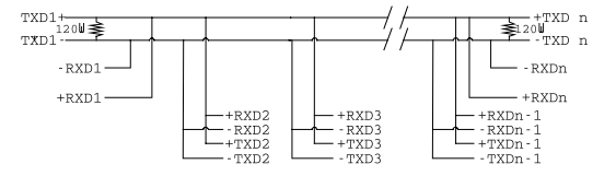
BOTH ends of MAIN line terminated in characteristic impedance, stubs off main line not impedance, since both ends receive. The twisted pair ends are wired to both RXD+ & TXD+ and RXD- & TXD- at each RS-485 device!
RS-485 Many Talkers - Many Listeners, Full Duplex
The RS-485 many talkers, many listeners, Full Duplex system can be used when all the RS-485 devices have separate Transmit and Receive channels. There is NO multiplexing of the TXD and RXD signals on the same device. This system is especially useful when there is no flow control available on the PC, usually due to the use of a third party communications program that prevents the use of the RTS signal as a "transmit enable" control. It can be used in the following situations:
a) The PC is connected to only ONE RS-485 device.
b) The PC is communicating with several RS-485 devices that are each able to recognize and respond to their own unique address. The RS-485 devices only drive their TXD lines when they are responding to requests from the PC to send data. In effect, the RS-485 device's address and the command it receives is used to control access to the devices TXD channel.
This is a Full Duplex system. Two twisted pair cables are required. One twisted pair, is the PC's TXD channel, it carries the data sent from the PC's TXD outputs to the RXD inputs of each of the RS-485 devices. The second twisted pair, is the Devices TXD channel, it carries the data sent from each of the devices' TXD outputs to the RXD inputs of the PC. The advantages of this system are great, since no new communications, software is needed, and the PC can talk and listen at the same time. In effect, the handshaking is performed by the intelligence of the RS-485 devices attached to the PC. When wired as below, the PC can transmit data at any time and all the RS-485 devices #1 to #n simultaneously receive it. Only one of the RS-485 devices may talk, i.e. transmit data, at any one time. Each RS-485 device recognizes commands and data addressed to it; it only talks when the PC commands it to do so. When the RS-485 device receives the command to talk from the PC, it gates its TXD drivers on, sends the data down the device TXD channel, and disables its TXD drivers. The other RS-485 devices remain in the 'receive only' mode when they are not being addressed, they do not transmit any data at all.
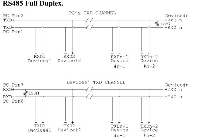
The receiver end of MAIN line terminated in characteristic impedance, stubs off the main not terminated.
RS-422 Serial Port Cables
Use screened twisted pair Belden cable 9729 and 9829, L type 2493 and 2919 cable to make the RS-422 connection. Unscreened Belden type 8795 may also be used in less noisy environments. The on board resistor networks terminate the receiving end of the twisted pair cable in its characteristic impedance.
RS-485 Serial Port Cables
For best noise immunity use twisted pair cables to make the RS-485 connection. In Half Duplex wiring only 1 twisted cable pair is needed. Two twisted pair cables are needed for Full Duplex communications. Use screened twisted pair Belden cable 9729 and 9829, UL type 2493 and 2919 cable to make the RS-485 connection. Terminate the twisted pair cable.
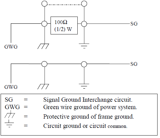
Optional Grounding Arrangements
Proper operation of the cable circuit, according to TIA EIA: 485 A (1995) requires that the cable ground shield is not connected directly to the equipment ground shield. A current limiting resistor should be used in series with the shield to avoid possible large current flow due to differences in ground potential. Any one of the methods shown below can do this.
The circuit common of the equipment is connected to protective ground, at one point only by a 100 Ohm, +/-20% resistor with a power dissipation rating of 1/2W. An additional provision may be made for the resistor to be bypassed with a strap to connect signal common and protective ground directly together when specific installation conditions necessitate.
For RS-422/485 products only, there is an additional tab in the Advanced Settings to allow you to change duplex mode.
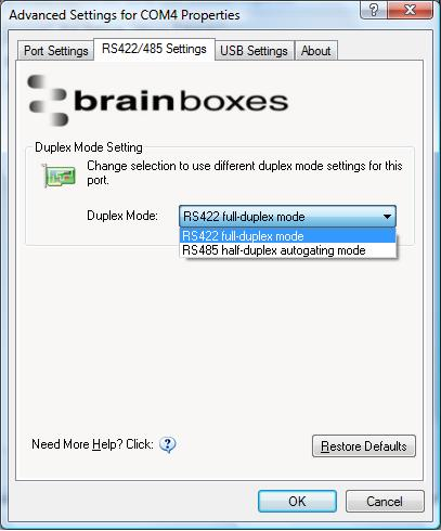
- The drop down list allows users to choose the desired RS-422/485 operations mode.
- Select "RS-422 full duplex mode" for Full Duplex communications.
- Select "RS-485 half duplex autogating mode" for Half Duplex communications.
- For further details on wiring, see Device Pinout
- Restore Defaults: Pressing this button will reset all settings on this Property Page back to the factory defaults of this device. The default settings for this Property Page are "RS-422 full duplex mode".
DTR/DSR Handshaking is not available on 422/485 devices.