
ED Hardware Features
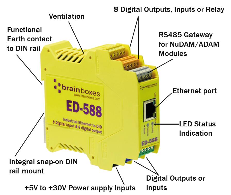
ED Range – Industrial
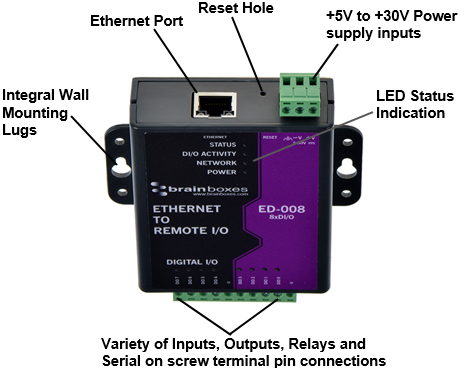
ED Range – Light Industrial
Usability Features
The ED range has been designed so that it is as easy as possible to wire up the input, output, relay, serial gateway and power wires to the terminal blocks and to connect the network cable:
- Removable screw terminal blocks make installation easier and quicker
- Colour coded terminal blocks and ports prevent an incorrect connection (Industrial only)
- Individually numbered pins simplify the wiring and removes confusion (Industrial only)
- Smart Ethernet which automatically detects the polarity of the Ethernet connection so either a straight through or crossover Ethernet cable can be used
- Functional ground to DIN rail
- USB Power Option - Can use the 5 Volt power from any computer USB port via the optional cable accessory PW-650
Technical Specifications
Network Connection
- 10Base-T or 100Base-TX Ethernet connection
- Standard 8P8C ("RJ45") socket connector
- TCP/IP protocol stack
- DHCP or static IP address
- Automatic transmit/receive crossover detection
- 1500V magnetic isolation
Power
- Wide-range +5 to +30V DC
- 60mA@24V 1.4W Typical
- 120mA@24V 2.9W Max
- Reverse voltage protected
- ESD and surge protected
- Earthing connection point
Storage and Operating Environment Guidelines
| Specification | ED Range – Industrial | ED Range – Light Industrial |
|---|---|---|
| Operating Temperature | -30°C to +80°C | 0°C to +60°C |
| Storage Temperature | -40°C to +85°C | -40°C to +85°C |
| Humidity | 5% to 95% non-condensing | 5% to 95% non-condensing |
| Housing | IP 30 rated non-conducting polyamide case with integrated DIN rail mount | IP 30 rated non-conducting polyamide case with integrated DIN rail mount |
LED Indicators
There are 4 LEDs on the ED devices representing the status, gateway, Ethernet link and the activity:
| LED | Colour | Meaning |
|---|---|---|
| Status LED | Green | Device Ready |
| Flashing Yellow | Changing Settings | |
| Flashing between Red & Green | Querying IP | |
| Flashing Green and Red | User performing Hard Reset | |
| Flashing between Green & Red/Yellow | IP address diagnostic | |
| Flashing between Green & Yellow | Initialization diagnostic | |
| Gateway | Flashing Red | RS-485 Comms error |
| Flashing Green | RS-485 | |
| Link LED | Green light on | Network Link Established |
| Flashing Green | Network Data RX/TX | |
| Activity | Flashing Green | Output set / Input Read |
| Flashing Red | Output overload |
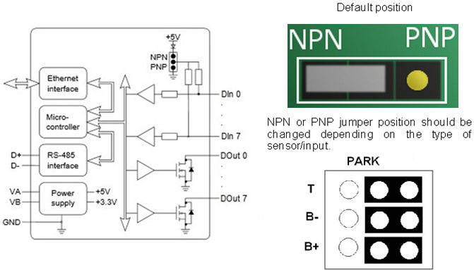
Circuit Diagrams
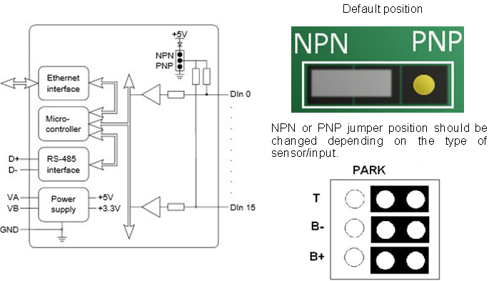
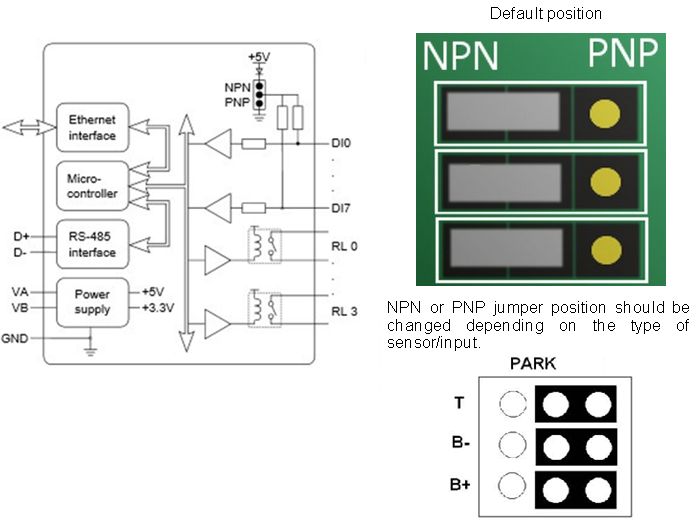
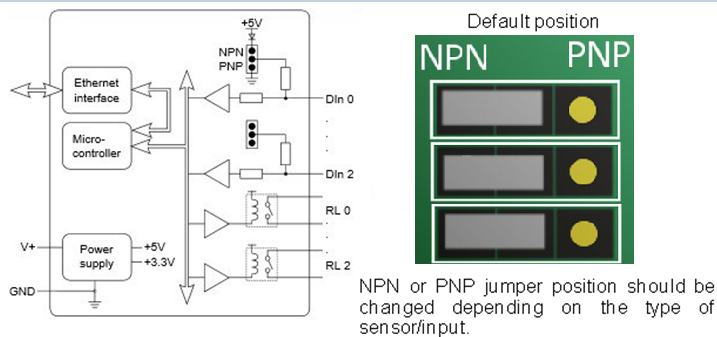
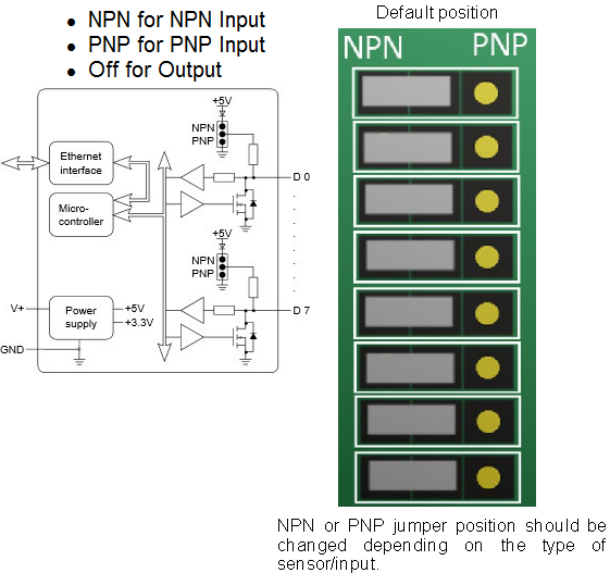
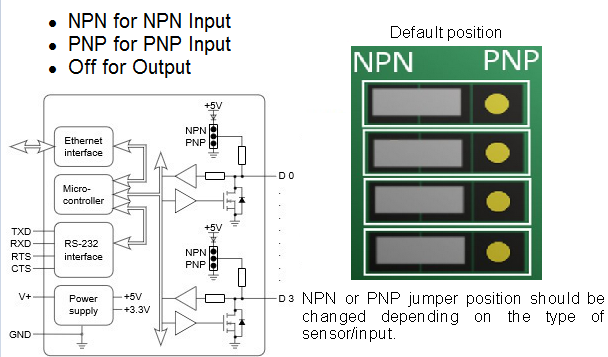
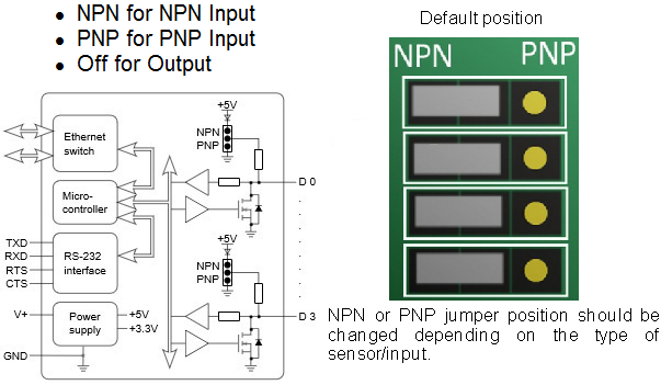
As long as you have the relevant jumper set to the 'NPN' position, you do not need an external power supply to use a contact switch. The NPN jumper position puts a pull-up resistor on the input so that you can just wire the switch between the input and ground.
For ED-588, ED-527, ED-516, ED-504, ED-538:
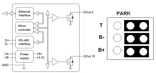
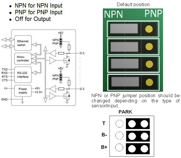
When in RS422/485 mode, there are biasing jumpers for Biasing (B+ and B-) and for Terminating Resistor (T).
These are factory default set in the ON position (Biasing and Terminating Resistor Enabled). If these jumpers are in the PARK position, then Biasing and Terminating Resistor is Disabled.
ED-588
ED-516
ED-527
ED-538
ED-038
ED-008
ED-004
ED-204
ED-504
Pin Outs
- Functional Ground is the EARTH connection through the DIN rail that the ED-5xx and ES-5xx is attached to. This Functional Ground (EARTH) on the ED-5xx is on PIN 5 of the BLACK power connector.
- Power Ground is the low side (0V) of the power input. Connected directly to PIN 1 and PIN 4 of the BLACK power input connector.
- Signal Ground is applicable to those ED/ES products which have a serial gateway or serial port. This is the ground associated with the data transmission signals.
ED-516: 16 Digital Inputs
| Type of Port | Terminal Block | Pin 1 | Pin 2 | Pin 3 | Pin 4 | Pin 5 |
|---|---|---|---|---|---|---|
| Digital In | Yellow | -V | DIn 0 | DIn 1 | DIn 2 | DIn 3 |
| Digital In | Orange | -V | DIn 4 | DIn 5 | DIn 6 | DIn 7 |
| Expansion | Grey | SIG GND | RS-485 D- | RS-485 D+ | RS-485 D+ | RS-485 D- |
| Digital In | Green | -V | DIn 8 | DIn 9 | DIn 10 | DIn 11 |
| Digital In | Blue | -V | DIn 12 | DIn 13 | DIn 14 | DIn 15 |
| Power | Black | -V | +VA | +VB | -V | Func. GND |
ED-527: 16 Digital Outputs
| Type of Port | Terminal Block | Pin 1 | Pin 2 | Pin 3 | Pin 4 | Pin 5 |
|---|---|---|---|---|---|---|
| Digital Out | Yellow | -V | DOut 0 | DOut 1 | DOut 2 | DOut 3 |
| Digital Out | Orange | -V | DOut 4 | DOut 5 | DOut 6 | DOut 7 |
| Expansion | Grey | SIG GND | RS-485 D- | RS-485 D+ | RS-485 D+ | RS-485 D- |
| Digital Out | Green | -V | DOut 8 | DOut 9 | DOut 10 | DOut 11 |
| Digital Out | Blue | -V | DOut 12 | DOut 13 | DOut 14 | DOut 15 |
| Power | Black | -V | +VA | +VB | -V | Func. GND |
ED-538: 4 Relays and 8 Digital Inputs
| Type of Port | Terminal Block | Pin 1 | Pin 2 | Pin 3 | Pin 4 | Pin 5 |
|---|---|---|---|---|---|---|
| Relay Out | Yellow | RL 0 COM | RL 0 N/O | RL 1 COM | RL 1 N/O | - |
| Relay Out | Orange | RL 2 COM | RL 2 N/O | RL 3 COM | RL 3 N/O | - |
| Expansion | Grey | SIG GND | RS-485 D- | RS-485 D+ | RS-485 D+ | RS-485 D- |
| Digital In | Green | -V | DIn 0 | DIn 1 | DIn 2 | DIn 3 |
| Digital In | Blue | -V | DIn 4 | DIn 5 | DIn 6 | DIn 7 |
| Power | Black | -V | +VA | +VB | -V | Func. GND |
ED-588: 8 Digital Outputs and 8 Digital Inputs
| Type of Port | Terminal Block | Pin 1 | Pin 2 | Pin 3 | Pin 4 | Pin 5 |
|---|---|---|---|---|---|---|
| Digital Out | Yellow | -V | DOut 0 | DOut 1 | DOut 2 | DOut 3 |
| Digital Out | Orange | -V | DOut 4 | DOut 5 | DOut 6 | DOut 7 |
| Expansion | Grey | SIG GND | RS-485 D- | RS-485 D+ | RS-485 D+ | RS-485 D- |
| Digital In | Green | -V | DIn 0 | DIn 1 | DIn 2 | DIn 3 |
| Digital In | Blue | -V | DIn 4 | DIn 5 | DIn 6 | DIn 7 |
| Power | Black | -V | +VA | +VB | -V | Func. GND |
ED-504: 4 Digital IO & RS232/422/485
| Type of Port | Terminal Block | Pin 1 | Pin 2 | Pin 3 | Pin 4 | Pin 5 |
|---|---|---|---|---|---|---|
| RS232 | Yellow | SIG GND | CTS | RXD | RTS | TXD |
| RS422 | Yellow | SIG GND | RXD- | RXD+ | TXD+ | TXD- |
| RS485 | Yellow | SIG GND | DATA+ | DATA- | ||
| Digital IO | Green | -V | DIO 0 | DIO 1 | DIO 2 | DIO 3 |
| Power | Black | -V | +VA | +VB | -V | Func. GND |
Light Industrial Pinouts
ED-004
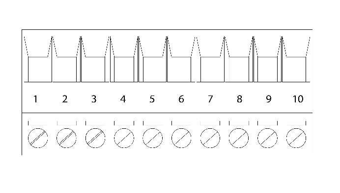
| Pin | 1 | 2 | 3 | 4 | 5 | 6 | 7 | 8 | 9 | 10 |
|---|---|---|---|---|---|---|---|---|---|---|
| Port | RS232 | Digital I/O | ||||||||
| Out | TxD | RxD | RTS | CTS | SIG GND | DIO 3 | DIO 2 | DIO 1 | DIO 0 | -V |
ED-008
| Pin | 1 | 2 | 3 | 4 | 5 | 6 | 7 | 8 | 9 | 10 |
|---|---|---|---|---|---|---|---|---|---|---|
| Port | Digital I/O | |||||||||
| Out | DIO 7 | DIO 6 | DIO 5 | DIO 4 | -V | DIO 3 | DIO 2 | DIO 1 | DIO 0 | -V |
ED-038
| Pin | 1 | 2 | 3 | 4 | 5 | 6 | 7 | 8 | 9 | 10 |
|---|---|---|---|---|---|---|---|---|---|---|
| Port | FORM A RELAY | Digital In | ||||||||
| Out | COM 2 | NO 2 | COM 1 | NO 1 | COM 0 | NO 0 | DIO 2 | DIO 1 | DIO 0 | -V |
ED-204
| Pin | 1 | 2 | 3 | 4 | 5 | 6 | 7 | 8 | 9 | 10 |
|---|---|---|---|---|---|---|---|---|---|---|
| Port | RS232 | Digital I/O | ||||||||
| Out | TxD | RxD | RTS | CTS | SIG GND | DIO 3 | DIO 2 | DIO 1 | DIO 0 | -V |
Terminal Block Connector Pinout (Light Industrial)
RS-232 Standard
The RS-232 standard was introduced in 1962 and is now widely established. RS-232 is a slow speed, short distance, single ended transmission system (i.e. only one wire per signal). Typical RS-232 maximum cable length is 50 feet.
Device Dimensions
Industrial Devices

Light Industrial Devices

Reset Button
Manual Reboot
- Press the reset button once
- The status LED will flash and after 5 seconds the device will reboot
- When the device is restarted, any connections you have had to the COM ports will need to be re-established
Manual Hard Restore
- Press and hold the reset button on the device for 5 seconds
- The status LED will flash red/green and the device will be restored to factory default settings
Manual Hard Restore will erase all your custom settings. See the Factory Default Settings section for details.
Input/Output Specification
ED Range – Industrial
Inputs: ED-588, ED-516, ED-538
| Specification | Details |
|---|---|
| NPN/PNP | One jumper configures all inputs as either pull up for NPN, active low, type sensors or pull down for PNP, active high, type sensors |
| Logic Level 0 | 0V to +1V maximum |
| Logic Level 1 | +3.5V to 30V maximum |
| Latched Inputs | Triggered by user programmable positive or negative edges, stays true until acknowledged |
| Counter Inputs | User programmable – counts positive or negative transitions 0-65335 |
Outputs: ED-588, ED-527
| Specification | Details |
|---|---|
| Maximum output current | Sinks up to 1Amp per pin 40V max load. Max combined load 4.0 Amps per ED device |
| Characteristic | Open drain output, protected MosFET with intelligent short circuit protection up to 36V. Over temperature shutdown: 175ºC typical 150ºC min |
| Maximum output load Voltage | 40V |
| ESD Protection | 16kV |
ED Range – Light Industrial
Inputs: ED-008, ED-038
| Specification | Details |
|---|---|
| NPN/PNP | One jumper configures each input as either pull up for NPN, active low, type sensors or pull down for PNP, active high, type sensors |
| Logic Level 0 | 0V to +1V maximum |
| Logic Level 1 | +3.5V to 30V maximum |
| Latched Inputs | Triggered by user programmable positive or negative edges, stays true until acknowledged |
| Counter Inputs | User programmable – counts positive or negative transitions 0-65335 |
Outputs: ED-008
| Specification | Details |
|---|---|
| Maximum output current | Sinks up to 0.85Amp per pin 30V max load. Max combined load 4.0 Amps per ED device |
| Characteristic | Open drain output, protected MosFET with intelligent short circuit protection |
| Maximum output load Voltage | 30V |
| ESD Protection | 16kV |
Relay Information (ED-538, ED-038 Only)
A relay is an electrically operated switch used to control a circuit by a low power signal giving complete electrical isolation between the control and the controlled circuits. Relays are often used where several circuits must be controlled by one signal.

| Specification | Details |
|---|---|
| Relay Type | Form A (SPST-NO: Single Pole Single Throw, Normally Open). When power is removed from the ED-538/ED-038, the relay is open |
| Contact Rating | 5A @ 30VDC, 5A @ 250VAC |
| Contact Resistance | 100mΩ max. (at 1A 24VDC) |
| Relay Endurance | 100,000 operations at 3A, 30 operations/min, resistive AC load. 50,000 operations at 5A, 20 operations/min, resistive AC load |
ED-538 Relay Pinout
| Terminal Block | Pin 1 | Pin 2 | Pin 3 | Pin 4 | Pin 5 |
|---|---|---|---|---|---|
| Yellow | RL 0 COM | RL 0 N/O | RL 1 COM | RL 1 N/O | - |
| Orange | RL 2 COM | RL 2 N/O | RL 3 COM | RL 3 N/O | - |
ED-038 Relay Pinout
| Pin 1 | Pin 2 | Pin 3 | Pin 4 | Pin 5 | Pin 6 |
|---|---|---|---|---|---|
| COM 3 | NO 3 | COM 2 | NO 2 | COM 1 | NO 1 |
| Relay 3 | Relay 2 | Relay 1 |
Firewall Exceptions and Port Numbers
When using the ED Devices with a firewall you may need to manually add the exception entries and port numbers to the firewall list.
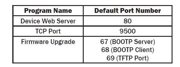
Default Windows Firewall Exception entries:
- Brainboxes Boost.IO Suite
- Brainboxes Boost.IO Suite (Device Discovery) - Except Windows XP32 & 64 bits
- UPnP Framework (Windows XP32 & 64 bits)
- Network Discovery (Windows 7 or later)