
ED Analogue Hardware Features
ED Range - Industrial
The ED range has been designed so that it is as easy as possible to wire up the input/output, serial expansion and power wires to the terminal blocks and to connect the network cable.
Usability Features
- Removable screw terminal blocks make installation easier and quicker
- Colour coded terminal blocks and ports prevent an incorrect connection
- Individually numbered pins simplify the wiring and removes confusion
- Smart Ethernet automatically detects the polarity of the Ethernet connection so either a straight through or crossover Ethernet cable can be used
- Built-in functional ground connection to DIN rail
- Power input from 5-30V: dual redundant input enables two power sources to be connected
You can use the 5 Volt power from any computer USB port via the optional cable accessory PW-650.
Technical Specifications
Network Connection
- 10Base-T or 100Base-TX Ethernet connection
- Standard 8P8C ("RJ45") socket connector
- TCP/IP protocol stack
- DHCP or static IP address
- Automatic transmit/receive crossover detection
- 1500V magnetic isolation
Power
- Wide-range +5 to +30V DC
- 60mA@24V 1.4W Typical
- 120mA@24V 2.9W Max
- Reverse voltage protected
- ESD and surge protected
- Earthing connection point
Storage and Operating Environment Guidelines
| Specification | ED Range - Industrial |
|---|---|
| Operating Temperature | -30°C to +80°C |
| Storage Temperature | -40°C to +85°C |
| Humidity | 5% to 95% non-condensing |
| Housing | IP 20 rated non-conducting polyamide case with integrated DIN rail mount |
LED Indicators
There are 4 LEDs on the ED devices representing the status, expansion port, Ethernet link and the activity.
| LED | Colour/State | Meaning |
|---|---|---|
| Status LED | Green | Device Ready |
| Flashing Yellow | Changing Settings | |
| Flashing between Red & Green | Querying IP | |
| Flashing Green and Red | User performing Hard Reset | |
| Flashing between Green & Red/Yellow | IP address diagnostic | |
| Flashing between Green & Yellow | Initialization diagnostic | |
| Expansion | Flashing Red | RS-485 Comms error |
| Flashing Green | RS-485 | |
| Link LED | Green light on | Network Link Established |
| Flashing Green | Network Data RX/TX | |
| Activity | Flashing Green | Input Read |
| Flashing Red | Input Error |
Block Diagrams
ED-549
The ED-549 provides 8 analogue input channels with differential voltage or current sensing capabilities.
ED-560
The ED-560 provides 4 analogue output channels with voltage or current output capabilities.
Block diagram images are available in the original documentation. The diagrams show the internal architecture including the ADC/DAC, microcontroller, Ethernet interface, and terminal connections.
Pin-outs
Ground Connections
Functional Ground is a ground connection for the reduction of electrical noise. It is different from a Protective Earth which is for safety purposes, and is not required on these products due to their low operating voltage. The Functional Ground (earth) on the ED-5xx product series is on pin 5 of the black power connector. There is also a contact clip on the back of the product case which connects the Functional Ground to the DIN rail the product is mounted on. DIN rails are typically grounded, in which case it is not necessary to wire to the Functional Ground terminal as well.
Power Ground (GND, -V) is the low side or "0V" of the power input. The terminals labelled GND on the pin-out tables are connected directly to the -V terminals of the BLACK power input connector and are thus connected to the low side of the power supply/supplies.
Analogue Ground (AGND) is the ground for the analogue input or output circuitry. It is isolated from power ground to reduce noise and prevent ground loops, but can be connected to power ground if the system design requires it.
- For the ED-560, AGND is the reference voltage for the single-ended voltage outputs and the loop 0V terminal for current-mode outputs
- For the ED-549, the analogue measurements are not directly dependent on the AGND connection (voltage mode measures the voltage between the AIn+ and the AIn- terminals, and current mode measures the current flowing through the AIn+ and AIn- terminals) -- but AGND is still required to be connected to a suitable 0V point on the signal-sourcing equipment, such that all the AIn+ and AIn- terminals are within +/-11V of AGND. AGND is also a suitable connection point for any cable shield or drain wires.
ED-549 Pin-outs
| Terminal Block | Pin 1 | Pin 2 | Pin 3 | Pin 4 | Pin 5 |
|---|---|---|---|---|---|
| Yellow | AGND | AIn 0- | AIn 0+ | AIn 1- | AIn 1+ |
| Orange | AGND | AIn 2- | AIn 2+ | AIn 3- | AIn 3+ |
| Grey | GND | RS-485 D- | RS-485 D+ | RS-485 D+ | RS-485 D- |
| Green | AGND | AIn 4- | AIn 4+ | AIn 5- | AIn 5+ |
| Blue | AGND | AIn 6- | AIn 6+ | AIn 7- | AIn 7+ |
| Black | -V | +VA | +VB | -V | Func GND |
ED-560 Pin-outs
| Terminal Block | Pin 1 | Pin 2 | Pin 3 | Pin 4 | Pin 5 |
|---|---|---|---|---|---|
| Yellow | AGND | VOut 0 | VOut 1 | IOut 0 | IOut 1 |
| Grey | GND | RS-485 D- | RS-485 D+ | RS-485 D+ | RS-485 D- |
| Green | AGND | VOut 2 | VOut 3 | IOut 2 | IOut 3 |
| Black | -V | +VA | +VB | -V | Func GND |
Device Dimensions
ED-549
Dimensions are provided in the original documentation showing the physical size of the ED-549 device suitable for DIN rail mounting.
ED-560
Dimensions are provided in the original documentation showing the physical size of the ED-560 device suitable for DIN rail mounting.
Reset Button
The reset button is behind the hole marked 'Reset' on the front panel. To press it, use a straightened-out paper clip or similar tool.
Manual Reboot
- Press the reset button once
- The status LED will flash and after 5 seconds the device will reboot
- When the device is restarted, any connections you have had to the COM ports will need to be re-established
Manual Hard Restore
- Press and hold the reset button on the device for 5 seconds
- The status LED will flash red/green and the device will be restored to factory default settings
Any user calibration will be erased, and the calibration will return to the factory calibration as originally supplied to you. See the Factory Default Settings section for details.
Specification
ED-549 Input Specification
The ED-549 provides eight analogue input channels, each of which is independently configurable as either a differential voltage input or a current-sense input.
Voltage Input Mode:
- Input impedance: minimum 10MΩ
- Full scale range options: +/-10V, +/-5V, +/-2.5V, +/-1V, +/-500mV, +/-250mV, +/-150mV or +/-75mV
Current Input Mode:
- 115Ω sense resistor
- Full scale range options: +/-20mA, 0-20mA or 4-20mA
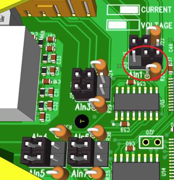
Jumper Configuration:
Each channel has a jumper block that allows it to be individually set for either voltage input mode or current input mode. The factory fitted configuration is that all 8 channels are set to voltage input mode.
- Jumper across left hand and central pins: high input impedance suitable for voltage input ranges
- Jumper across right hand and central pins: 115Ω sense resistor enabled suitable for current input ranges
Performance:
- Measurement rate: 12 measurements per second, divided between all enabled inputs
- Resolution: 16-bit
- Allowed single-ended voltage: within +/-11V of the AGND pins
- Accuracy: within 0.1% of full scale range at 25°C and 0.3% over -30°C to +80°C
- Common-mode rejection ratio (CMRR): over 120dB
- Normal-mode rejection ratio (NMRR): greater than 100dB at both 50Hz and 60Hz
ED-560 Output Specification
The device provides four analogue output channels, each of which has a voltage output terminal and a current output terminal. Each analogue output channel is independently configurable by software for:
- Calibrated 0-10V voltage output
- 0-20mA current output
- 4-20mA current output
When an output channel is configured for voltage output then the state of the current output signal is undefined; when an output channel is configured for current output then the state of the voltage output signal is undefined.
Voltage Output:
- Accuracy: within 10mV of the software-programmed value (0.1% of full-scale range)
- Load capability: sourcing between -5mA and 5mA
- Temperature drift of zero output: no larger than 30µV/°C
- Temperature drift of span: no larger than 25ppm/°C
Current Output:
- Type: 'sink' type, requires an external power source
- External power requirement: sufficient to provide at least 2.8V at the IOut terminal, up to a maximum of 30V
- Accuracy: within 16µA of the software-programmed value (0.1% of full-scale range)
- Temperature drift of zero output: no larger than 0.2µA/°C
- Temperature drift of span: no larger than 25ppm/°C
Settling Time:
- Voltage output: around 350µs (moving between 1V and 9V with oscilloscope probe load)
- Current output: around 4µs (moving between 2mA and 18mA)
Firewall Exceptions and Port Numbers
When using the ED Devices with a firewall you may need to manually add the exception entries and port numbers to the firewall list.
Default Port Numbers
| Function | Default Port Number |
|---|---|
| Device web server | TCP port 80 |
| ASCII protocol | TCP port 9500 |
| Modbus protocol | TCP port 502 |
| Firmware upgrade | UDP ports 67, 68, 69 |
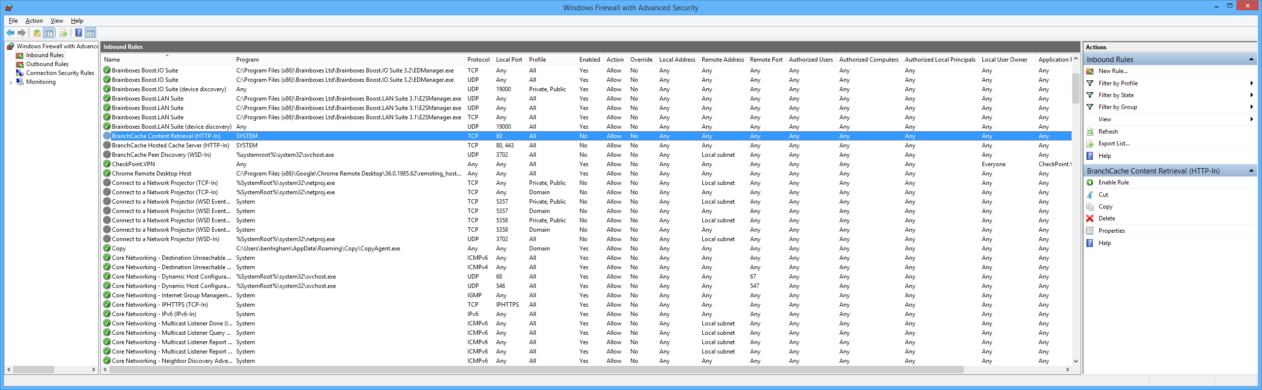
Windows Firewall Exceptions
The following exception entries are added by default during the installation of Boost.IO Manager:
- Brainboxes Boost.IO Suite
- Brainboxes Boost.IO Suite (Device Discovery)
- UPnP Framework (Windows XP 32 & 64 bits)
- Network Discovery (Windows 7 or later)
If you are using other anti-virus or firewall software you may need to add these exceptions into the anti-virus and firewalls you have installed.