
ED Analogue Web Configuration Pages
Introduction
The web configuration pages for the ED device allow you to configure all the settings on the device and view the status of the device. To access the web configuration pages, type the IP address of the device into a web browser. To find the IP address of your device, see Finding and Installing an ED Device.
In the top right corner of every page there will be a box that displays information about your device. It will show you the model, firmware version, MAC address, device name, location (if entered) and how long the device has been powered on for.
We recommend that you use Internet Explorer Version 7 and above, or any modern web browser.
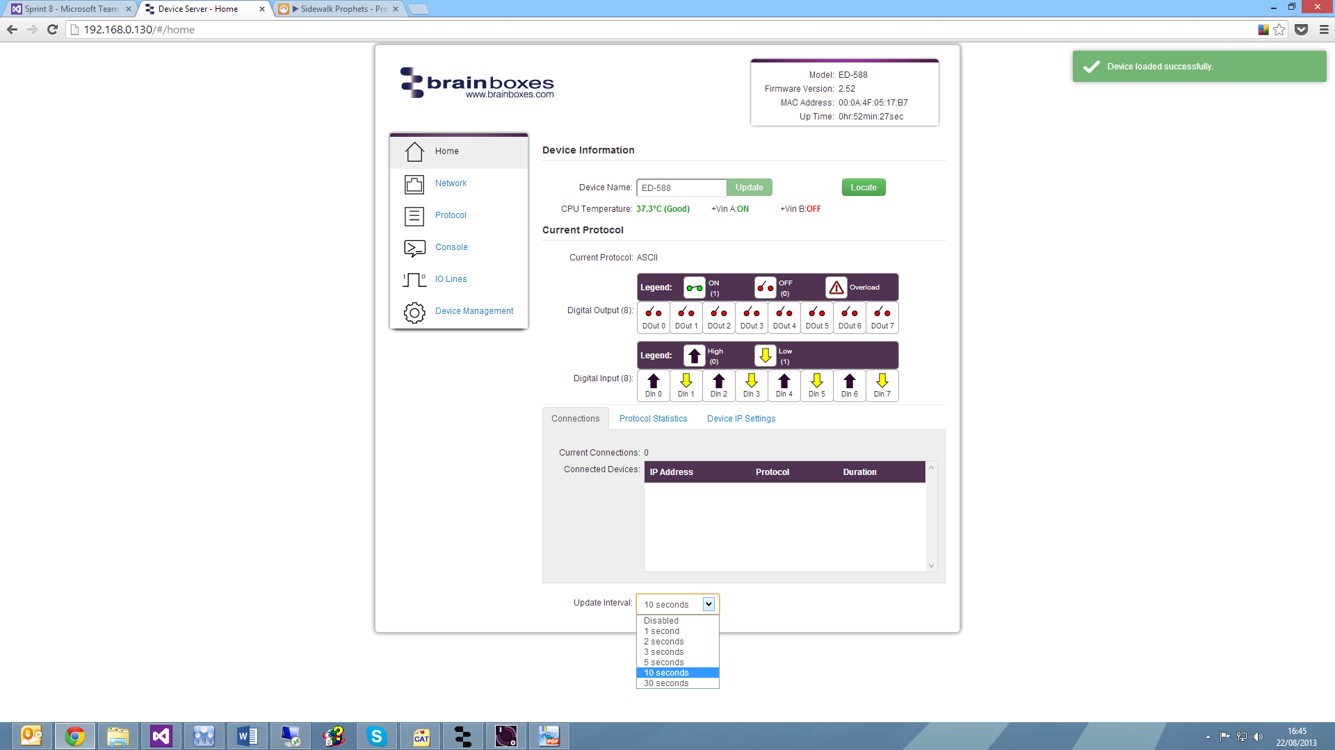
Home Page
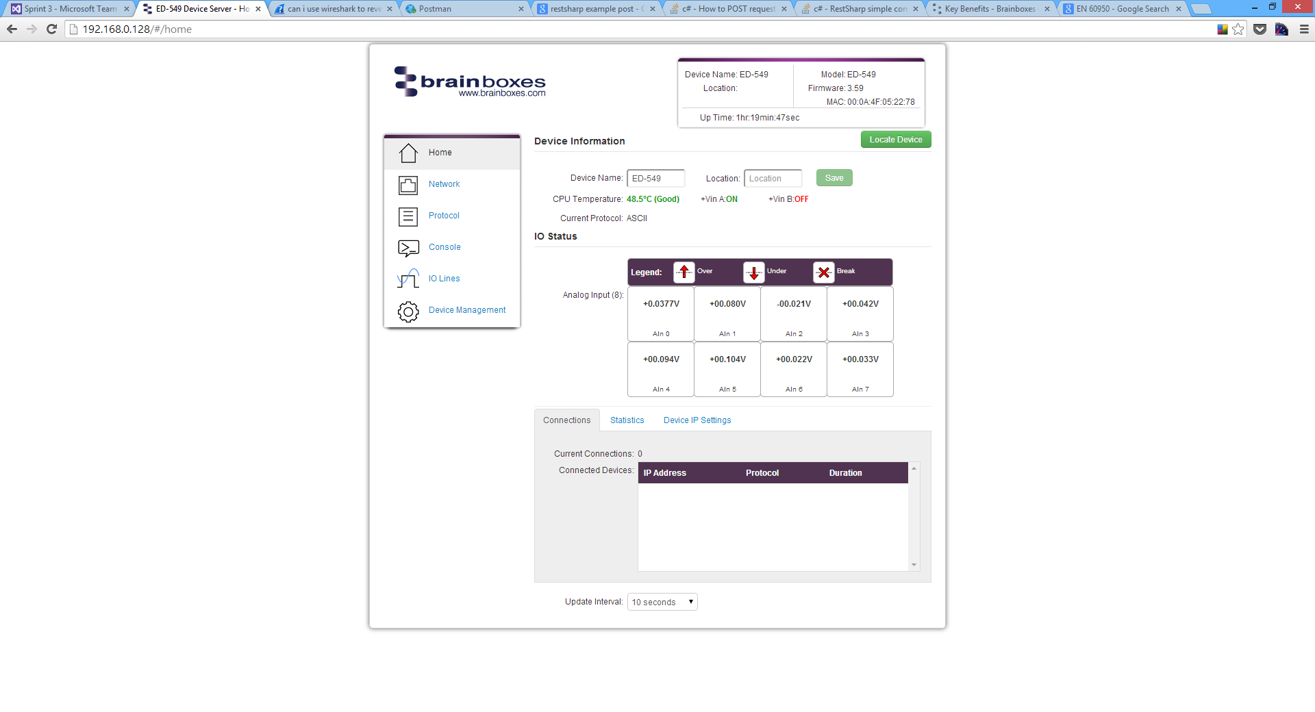
The Home page is the default page that loads when you enter the IP address of the device into a web browser. This page mainly displays information about the device and a visual display of the states of the input lines.
Locate Button
When the Locate Device button is pressed, all the LEDs on the front of the device will flash for 10 seconds. If you have a number of devices next to each other on a DIN rail, you may not be able to see the sticker on the side to identify the devices. Using the Locate button will allow you to clearly see which device you are configuring on the DIN rail without having to remove the device.
Device Information
Under the Device Information section is a text box which shows the current device name. This is the name that you can use to identify the device on your network. By default the device name is set to the product name but this can be changed by typing the name you would like into the text box and clicking Save.
To the right of the Device Name is the Location. The Location is blank by default but the location of the device can be added to help identify where the device is physically located.
Below this is the CPU temperature and status of the power supplies. The temperature will be displayed in green unless the CPU is getting hotter than it should, in which case the temperature will be displayed in red.
Also displayed is the state of both power inputs, +VA and +VB. The state will either be on or off, depending on whether they have power or not.
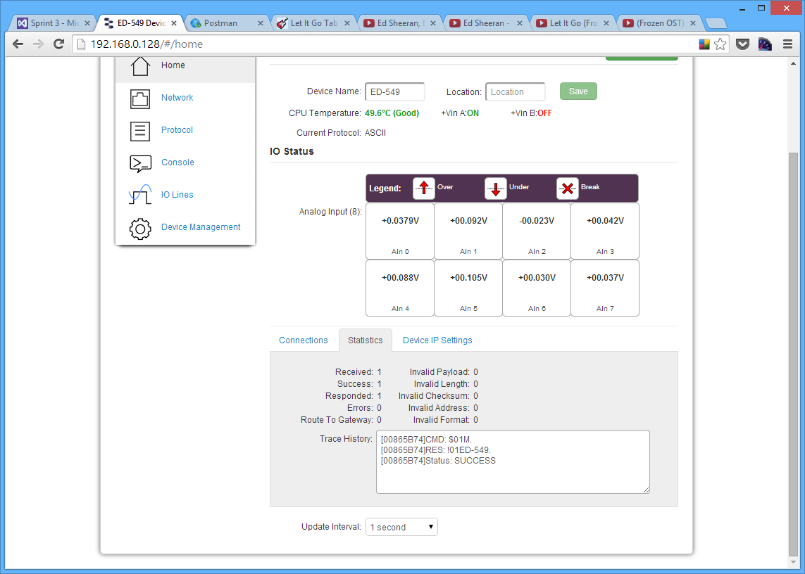
IO Status
The IO Status section displays the state of the Analogue Inputs.
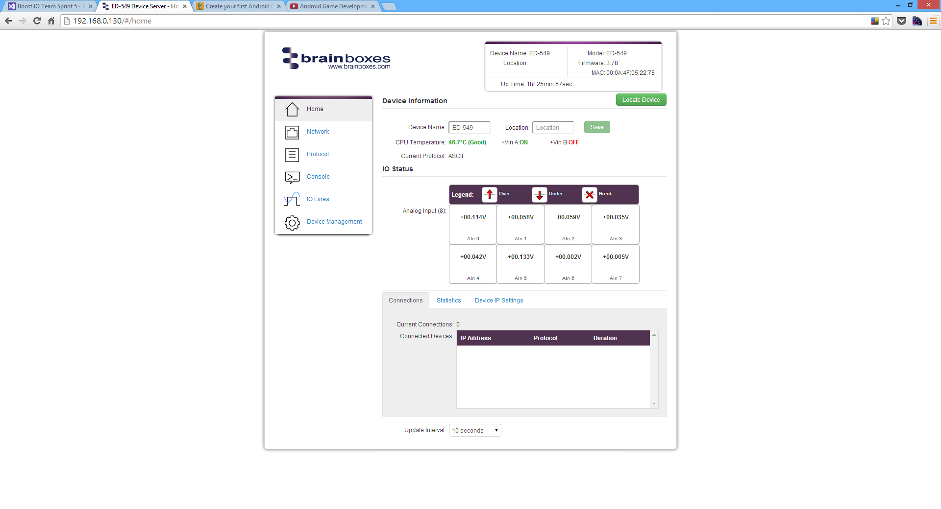
If the value read from the channel is within the full scale range then that value will be displayed in the appropriate position for that channel. If the value is over the full scale range then the Over symbol will be displayed for that channel, if the value is under the full scale range the Under symbol will be displayed, and if there is an input error (such as an excessive common-mode voltage) the Break symbol will be displayed.
The most common cause of an input error is the AGND terminal not being connected to a suitable point.
Connections Tab
The Connections tab displays information about any active connections to the device including the protocol being used to connect and the length of time the connection has been established.
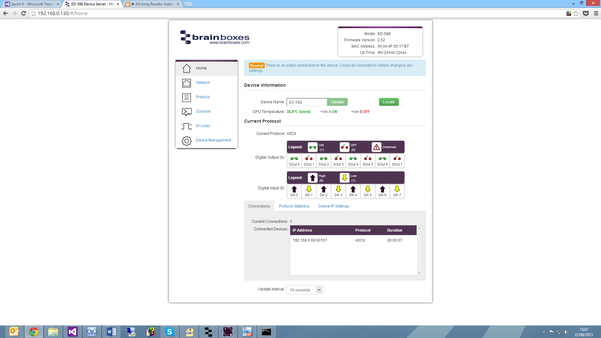
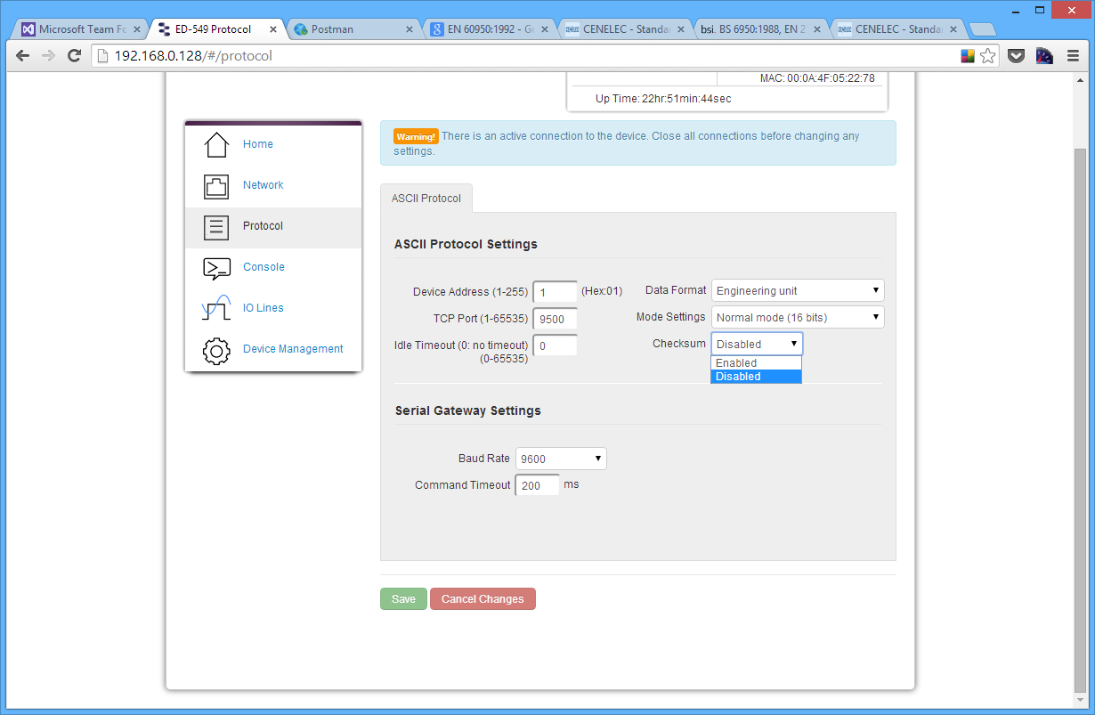
Also, when a connection is made there will be a warning at the top of every page. When changing some of the settings, the device is required to be restarted for the settings to be applied and the ED device cannot be restarted while a connection is being made to it.
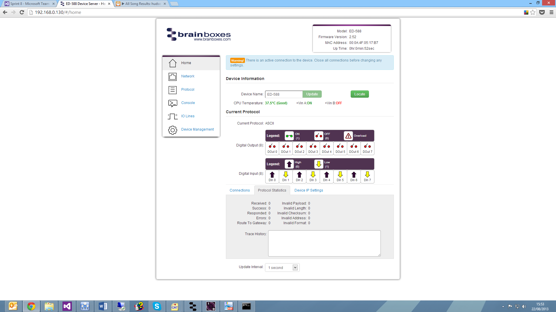
Statistics Tab
The Statistics tab will display information about the protocol commands that have been sent to the device since it was powered on, including a history of all the commands sent and the response of each command.
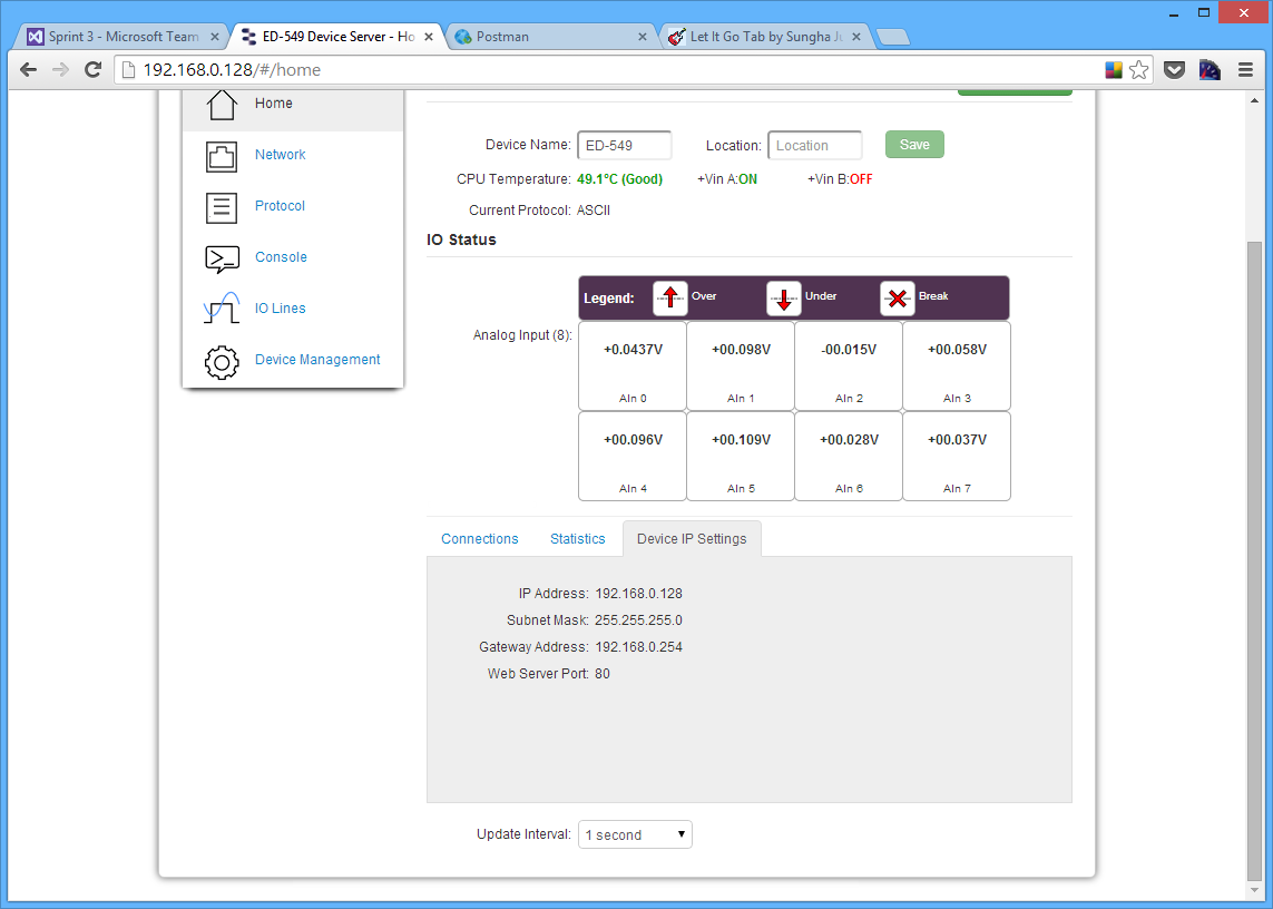
Device IP Settings Tab
Under the Device IP Settings tab there is information about the device's network settings. These settings can be changed on the Network page.
Update Interval
The Update Interval dropdown box controls how often the device information on the web configuration pages will be refreshed. For example, if set to 5 seconds, the web page will update all the information on the web pages every 5 seconds. If set to 'Disabled', the web page will not update these settings and you will have to refresh the page manually.
The update interval will only change the webpages refresh rate and does not affect the device's update time.
Network Page
The Network page allows you to configure all of the network settings of the ED device.
Network IP Address
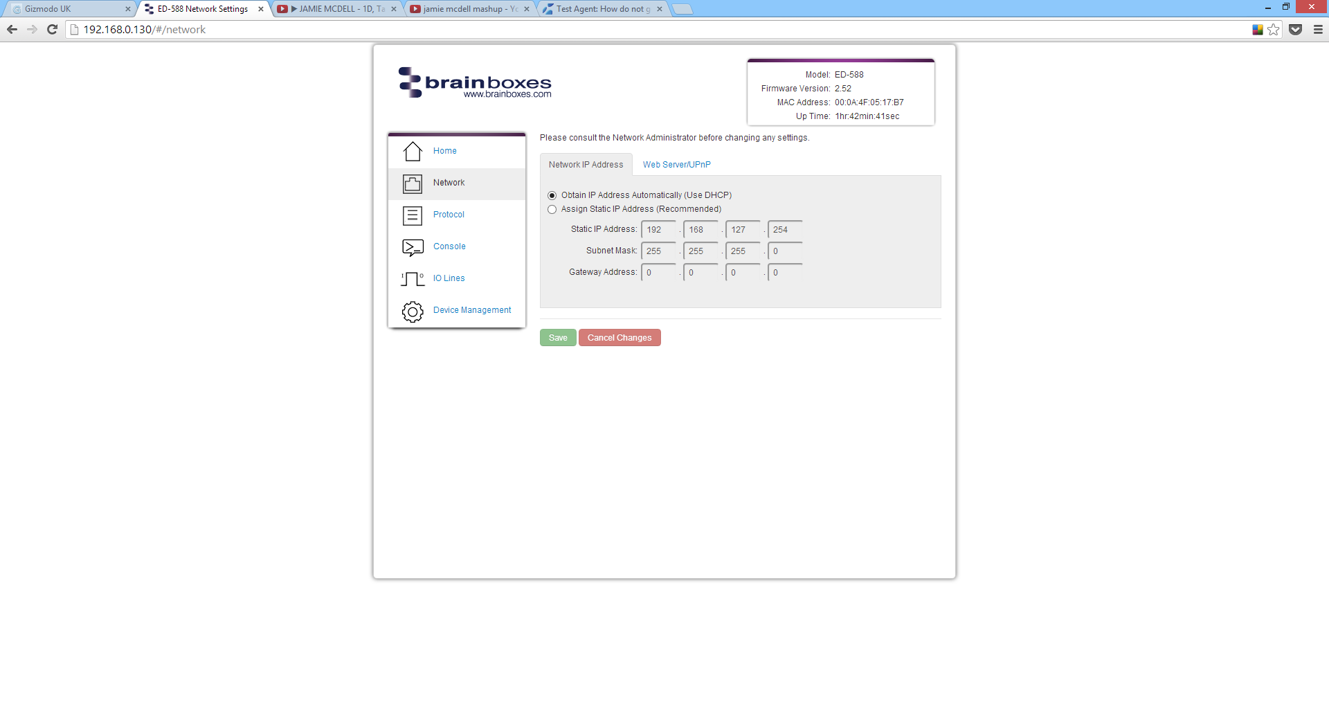
In the Network IP Address tab you can select whether the device is using DHCP, or a static IP address which you specify. By default the ED device is set to use DHCP to obtain an IP address automatically. If there is no DHCP server present, after 60 seconds the device will switch to a static IP address of 192.168.127.254.
Web Server/UPnP
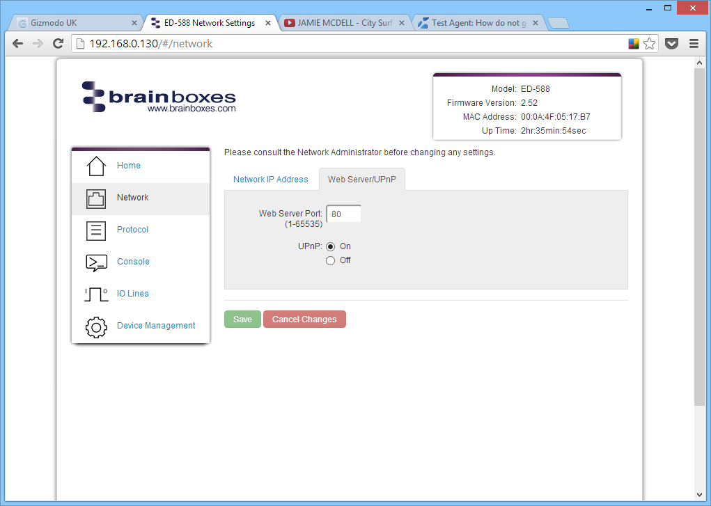
Under the Web Server/UPnP tab you can change the Web Server Port number and also turn UPnP on or off. The default Web Server Port number is 80.
Protocol Page
The protocol page has all of the ASCII settings and serial expansion settings.
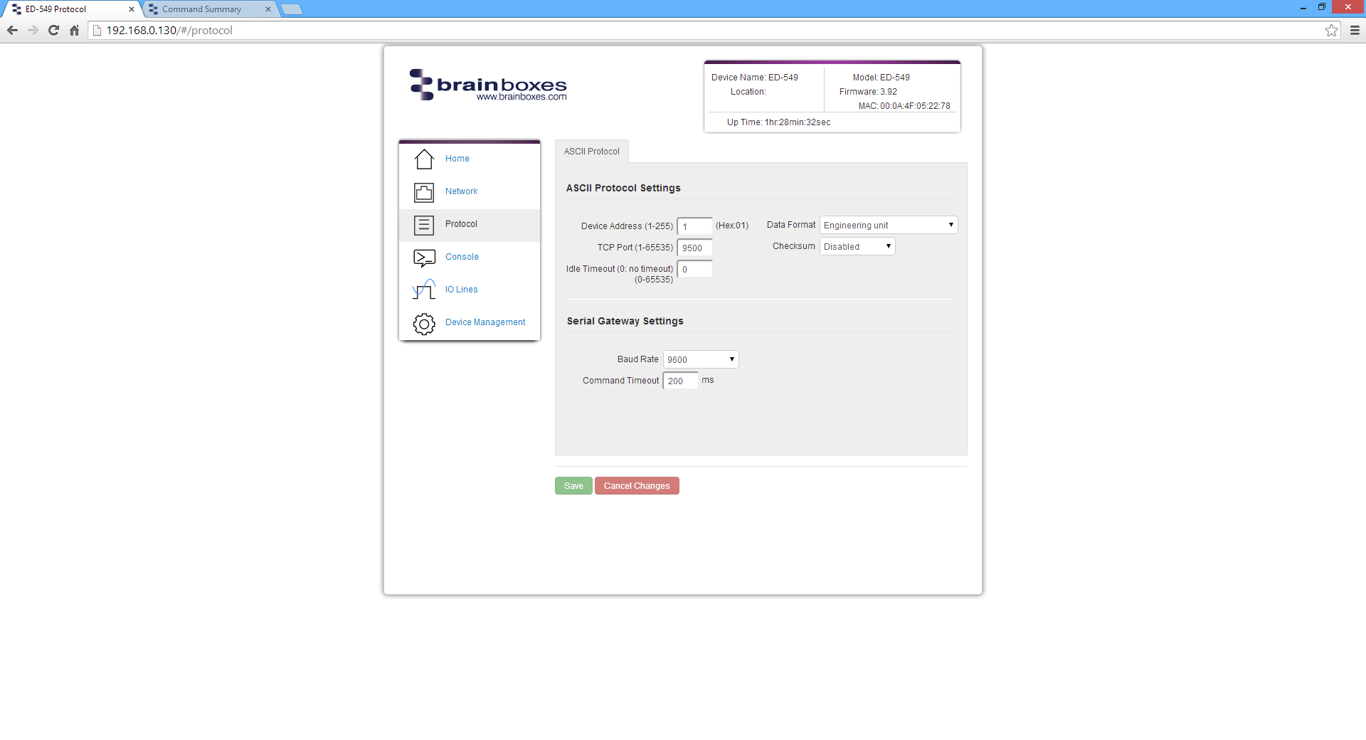
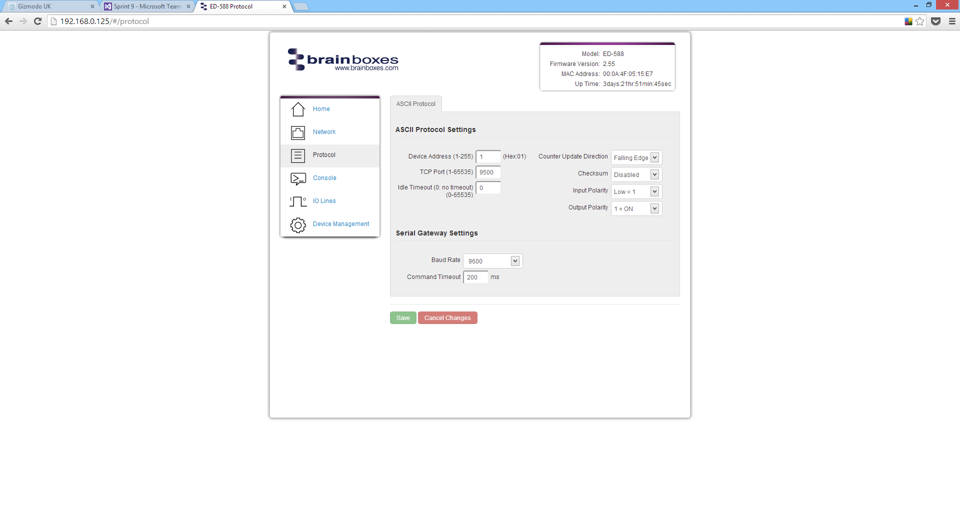
ASCII Protocol Settings
Device Address
The device address is a hexadecimal value which specifies the target device. If an ASCII command is being sent to a specific device, this address is used to specify which device the command is sent to. Also, some of the responses from the commands will contain a device address to indicate which device sent the response.
The number entered into the text box should be a decimal number between 1 and 255. Any decimal numbers entered will have their Hex value displayed to the right of the text box.
TCP Port
The TCP port is the network port that is used to connect to the device at the IP address that it's using. The default port number is 9500.
Idle Timeout
When the idle timeout is set, if there is no communication to the device for the specified period of time, the connection will be closed. The default idle connection is 0, meaning the connection will never be dropped automatically.
Data Format
The data format can be set to one of 3 options:
| Format | Description |
|---|---|
| Engineering unit | The actual value read from the analogue input line, displayed as voltage or current |
| % of full scale range (FSR) | The actual value as a percentage of the full scale range |
| 2's complement hexadecimal | The actual value converted into 2's complement hexadecimal (4 character hex value) |

Checksum
The purpose of the checksum is to help the PC and devices detect the communication errors that have corrupted the command strings. When the checksum is enabled all commands from the PC to the devices and all responses from the devices must contain a valid checksum otherwise the data is discarded. When the checksum is enabled, commands sent without a valid checksum will be ignored by the devices and the device will not respond to the host PC. By default, the checksum is disabled.
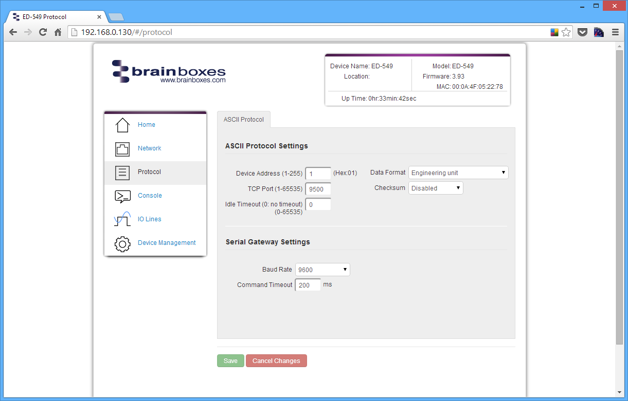
Serial Expansion Settings
The Expansion Port feature (available on ED-5XX models) allows the ED to send out ASCII commands on an RS485 bus to other ASCII protocol compatible devices such as NuDAM, eDAM and ADAM modules. The expansion port uses half duplex RS485 with 8 data bits, no parity and 1 stop bit.
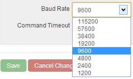
Baud Rate
The baud rate of the Expansion Port can be changed using the drop down box. The default baud rate is 9600.
Command Timeout
The Command Timeout option determines how long the ED device will wait for a response from the Serial Expansion once a command has been sent. If, after the specified time no response has been received through the expansion port then the ED device will stop waiting for a response. If a response does come in after the timeout value, the response will be discarded. The default timeout is 200 milliseconds.
Modbus TCP Settings
Brainboxes ED products by default are configured to use the ASCII protocol. To enable the Modbus protocol instead, select Modbus TCP from the Current Protocol drop-down menu, and check the Modbus TCP settings below.
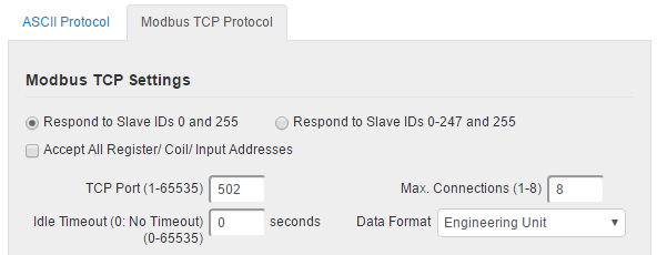
Slave ID option
In Modbus TCP the Slave ID is somewhat redundant as the destination of the message is already defined by the IP address of the TCP packet. Modbus-capable Brainboxes devices can be configured to either respond to Slave IDs 0 and 255, as required by the Modbus TCP specification, or to any valid Slave ID (0 to 247, and 255) for convenience.
Accept All Addresses
The usual operation of Modbus is that if a Modbus master attempts to access a register, coil or input address which is not used by the Modbus slave, the slave generates an error response and does not act on the request. If the Accept All Addresses option is enabled, the ED device will instead treat all register, coil or input addresses as valid: writes to unused addresses will be ignored, and reads from unused addresses will return zeroes.
TCP Port
The TCP port is a 16 bit number, 1-65535, used to identify the services or processes being used in networking communications. By convention, TCP port 502 is used by the Modbus protocol.
Idle Timeout value
When the Idle Timeout is set to a non-zero value, if there is no communication to the device for the specified period of time (in seconds), the connection will be closed. The default idle connection is 0, meaning that connections will not be closed on the basis of idle time. In compliance with the Modbus TCP standard, old connections may still be closed if the maximum number of connections has been reached and a new connection is requested.
Max Connections
The Max Connections field allows the user to select the maximum amount of simultaneous connections which can be made to their ED device at any one time. This field accepts any values between 1 (minimum) and 8 (maximum).
Data Format
There are two options available for the encoding of analogue values as integers in Modbus registers:
- As a value in Volts or milliAmps multiplied by a power of 10
- Scaled so that the range maximum maps to a round hexadecimal value
Click on the Save button when you have finished selecting the options you require.
Console Page
The Console Page contains the console window which allows ASCII commands to be sent straight to the device and be executed immediately. The response of the command is displayed in the console window in green. This is the simplest way to send ASCII commands to the ED device to either set or read settings.
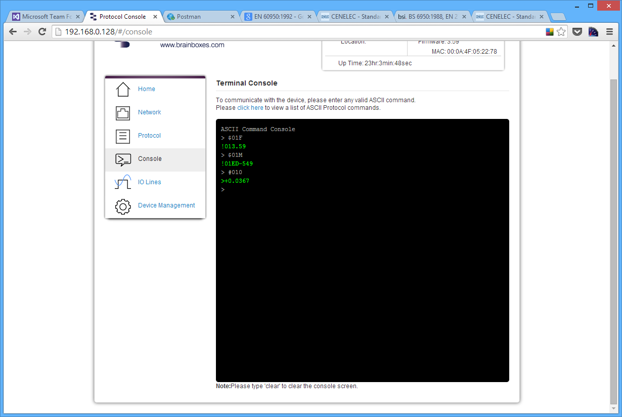
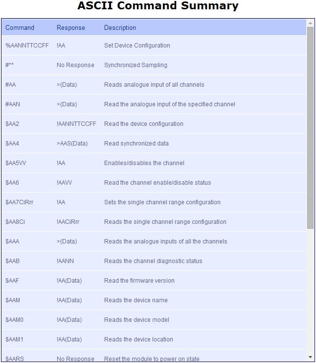
Also on the Console page is a link to a web view of all the ASCII protocol commands that can be sent to the device and a description of what each command does.
I/O Lines Page
Input I/O Lines Page (ED-549)
The IO Lines page lists all the input lines on the device and allows you to change their settings and calibrate them individually.
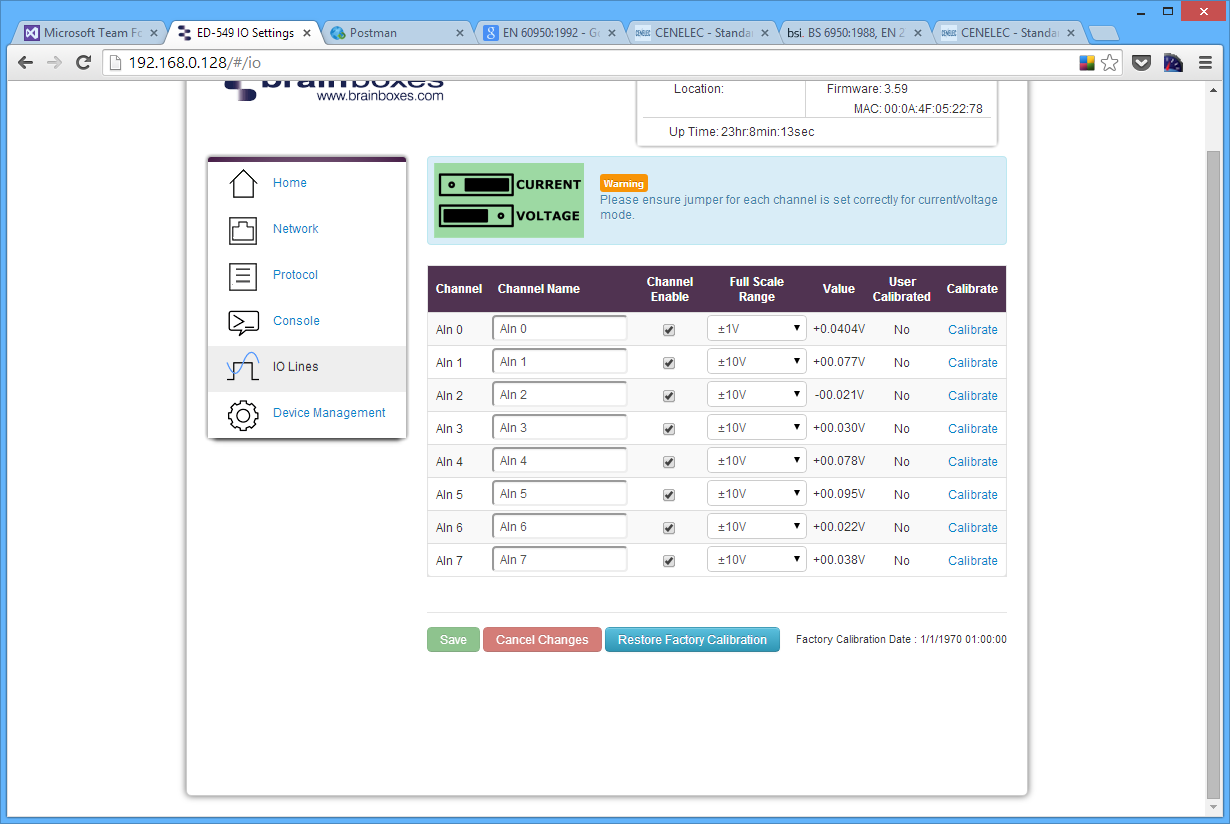
To overcome what would be a relatively long conversion latency between the time an input channel value is requested and returned, the Analogue Input range performs Analogue to Digital conversions continually across all enabled channels and so instantly returns the latest value taken. The IO Lines webpage can be used to disable any channels that are not in use, which will in turn make the refresh rate for the enabled channels higher, giving a more up to date Analogue input value.
Channel Name
The channel name box allows you to give a name to each of the channels individually. The name given to each of the channels will appear on the Home page of the web configuration pages in the IO status section.
Channel Enable
When the enable box is ticked then the channel is enabled and the value can be read from the channel. When the channel is disabled there will be no value displayed on the IO Lines page or in the IO Status section of the Home page.
Full Scale Range
The full scale range is the range of voltages or currents that the value will be displayed in.
Value
In the value column is the value which is read from each of the analogue lines. This is the same value that is displayed on the Home page and is adjusted according to the FSR and Data Format settings.
User Calibrated
Indicates which FSR range of the channel has been calibrated by the user and which channels have the factory calibration. A channel with "No" is using the factory calibration for the current FSR and channels with "Yes" have been calibrated by the user.
Calibrate
The calibrate button allows you to calibrate a specific channel of your ED device at the Full Scale Range that the channel is set to. The channel has to be calibrated for each FSR separately. You can look at the "User Calibrated" column to see which channels and FSRs have been calibrated manually and which are at the factory calibration.
Before you calibrate a channel the FSR needs to be set to the correct value. Once the FSR is set follow the steps below to calibrate a channel.
The following steps have the FSR set to +/-10V as an example.
- Click the Calibrate link on the channel that you want to calibrate.
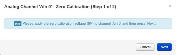
- Apply the zero calibration voltage specified in the dialogue box to the channel and then press Next. In this case the zero calibration voltage will be 0V.
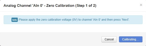
- The channel will then be calibrated to the zero calibration voltage supplied.
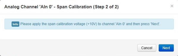
- Once the first stage is calibrated then the span calibration voltage needs to be applied to the channel. In this example the voltage required is +10V. Once the voltage is applied click Next.

- The channel will be calibrated to the span calibration voltage.
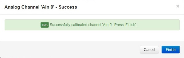
- Once the calibration is complete the success message will then show in the dialogue box. Click Finish to close the box. The channel will now be calibrated at that FSR range.
Restore Factory Calibration
The restore factory calibration button will erase any user calibration that has been applied to any of the channels and restore the factory calibration on all channels.
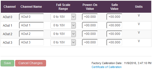
Output I/O Lines Page (ED-560)
The IO Lines page lists all the output lines on the device and allows you to change their settings individually.
Channel Name
The channel name box allows you to give a name to each of the channels. The name given to each of the channels will appear on the Home page of the web configuration pages in the IO status section.
Full Scale Range
The full scale range is the range of voltages or currents that the output will range over.
Power-On Value
The Power-On Value drop down boxes determine what state the output lines will go to every time the device is powered on. By default, all of the output lines will be set to the minimum output when the device is powered on.
For example, if the drop down boxes are set like below:
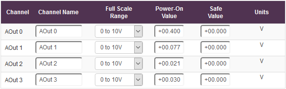
When the device is powered on with these settings, the output lines of the device will be:

Safe Value
The Safe Value drop down boxes set the state that the output lines will go to when the device goes into a Watchdog state. This ensures that if the controlling device crashes or there is a problem with the communication to the device, the output lines will always revert to a safe, known state.
When the safe value is set like the pattern below:
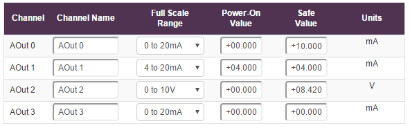
And the device goes into a Watchdog state for whatever reason, IOut 0 will automatically go to 10mA and VOut 2 will go to 8.42V.
If the device is in the Watchdog state there will be a message at the top of every configuration page warning about the state.

Device Management Page
The Device Management page has 2 options. The first is to restart your device and the second to restore the factory default settings of the device.
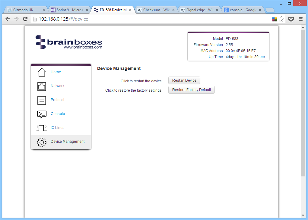
Restart Device
Clicking the Restart Device button will power cycle the device. In order to restart the device, there must be no connections being made to it. If there is a connection being made to the device, a warning message will be displayed asking you to close the connection before restarting the device.
Restore Factory Default
Clicking the Restore Factory Default button will revert all the settings on the device back to their factory default. Just like restarting the device, in order to restore the factory settings, there must be no connection to the device active.
Factory Default Settings
Network Settings
| Setting | Default Value |
|---|---|
| Network IP Address | DHCP Mode |
| Web Server Port | 80 |
ASCII Protocol Settings
| Setting | Default Value |
|---|---|
| Device Address | 01 |
| TCP Port | 9500 |
| Idle Timeout | 0 |
| Data Format | Engineering unit |
| Checksum | Disabled |
Serial Expansion Settings
| Setting | Default Value |
|---|---|
| Baud Rate | 9600 |
| Command Timeout | 200ms |
Modbus Protocol Settings
| Setting | Default Value |
|---|---|
| Slave IDs | Respond to IDs 0 and 255 only |
| Accept All Addresses | Disabled |
| TCP Port | 502 |
| Max connections | 8 |
| Idle Timeout | 0 (disabled) |
| Data Format | Engineering unit |