
ES Industrial Configuration Using the Webpage
The ES device can be accessed from any PC, tablet or phone that is connected to your network using any web browser as this does not require Boost.LAN Manager to be installed.
To access the ES device web page:
- Obtain the IP Address of the ES device.
- Enter the IP address into the address bar of your Web Browser and press the enter key.
- The ES device webpage interface should appear allowing you to view and configure the ES device settings.
ES devices store the device settings inside the device. When you access the webpage it gets these settings from the device. When you access the driver it gets the settings from the device too. If you have Boost.LAN closed and change a setting on the webpage, the device driver will not know that the settings have been changed on the webpage until Boost.LAN is opened. When Boost.LAN first opens it will update the settings of any installed devices. Therefore you need to open Boost.LAN manager after changing a setting on the webpage in order for the driver to use this new setting.
Home page
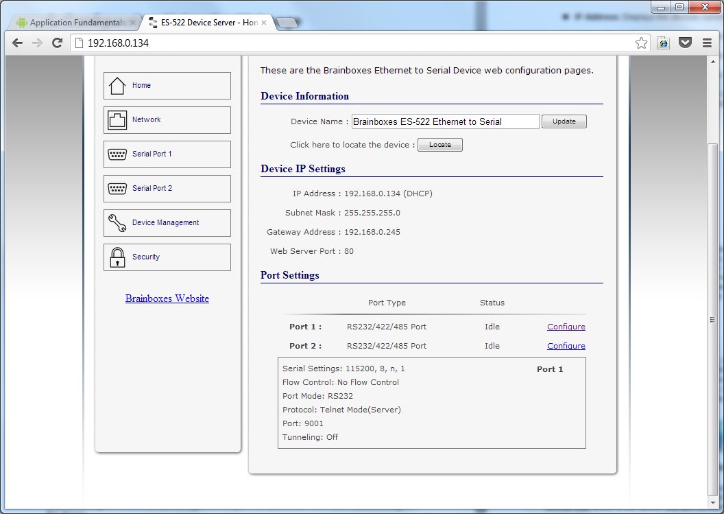
The Home page of the ES device is mainly for informational purposes whilst the other pages allow you to update various configuration options.
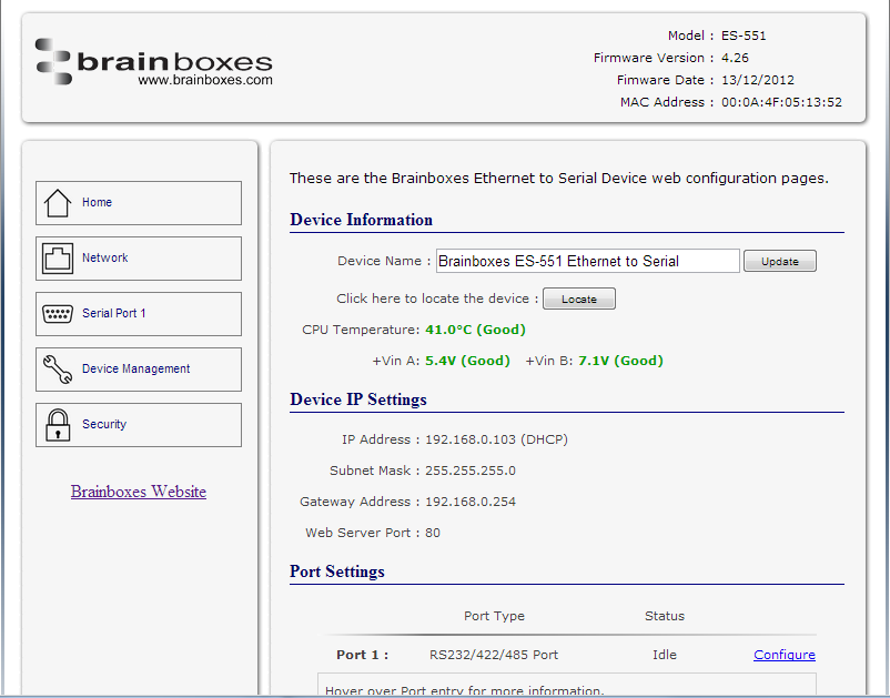
Device Information
-
Device Name: Here you can change the name the device will use on the network. To change the name, type the new name in the text box and click "Update"
-
CPU Temperature & Power Supply Voltage: Here you can see the CPU temperature in green. Below this are the power supply voltages. Vin A (first power supply) and Vin B (second power supply) are also shown in green.
-
Locate: The Locate button will cause all the LED's on the device to flash green for 5 seconds. This is useful if you have a line of industrial ES devices on a DIN rail and need to locate the physical device.
Device IP Settings
- IP Address: Displays the device's current IP Address
- Subnet Mask: Displays the device's current Subnet Mask
- Gateway Address: Displays the device's current Gateway Address
- Web Server Port: Displays the device's current Web Server Port number
Port Settings
Under the port settings section is listed the device's ports. Hovering over the port entry will display the ports serial settings. Clicking on the "Configure" link will take you to the serial port configuration pages where you can change the settings for the device.
Network Page
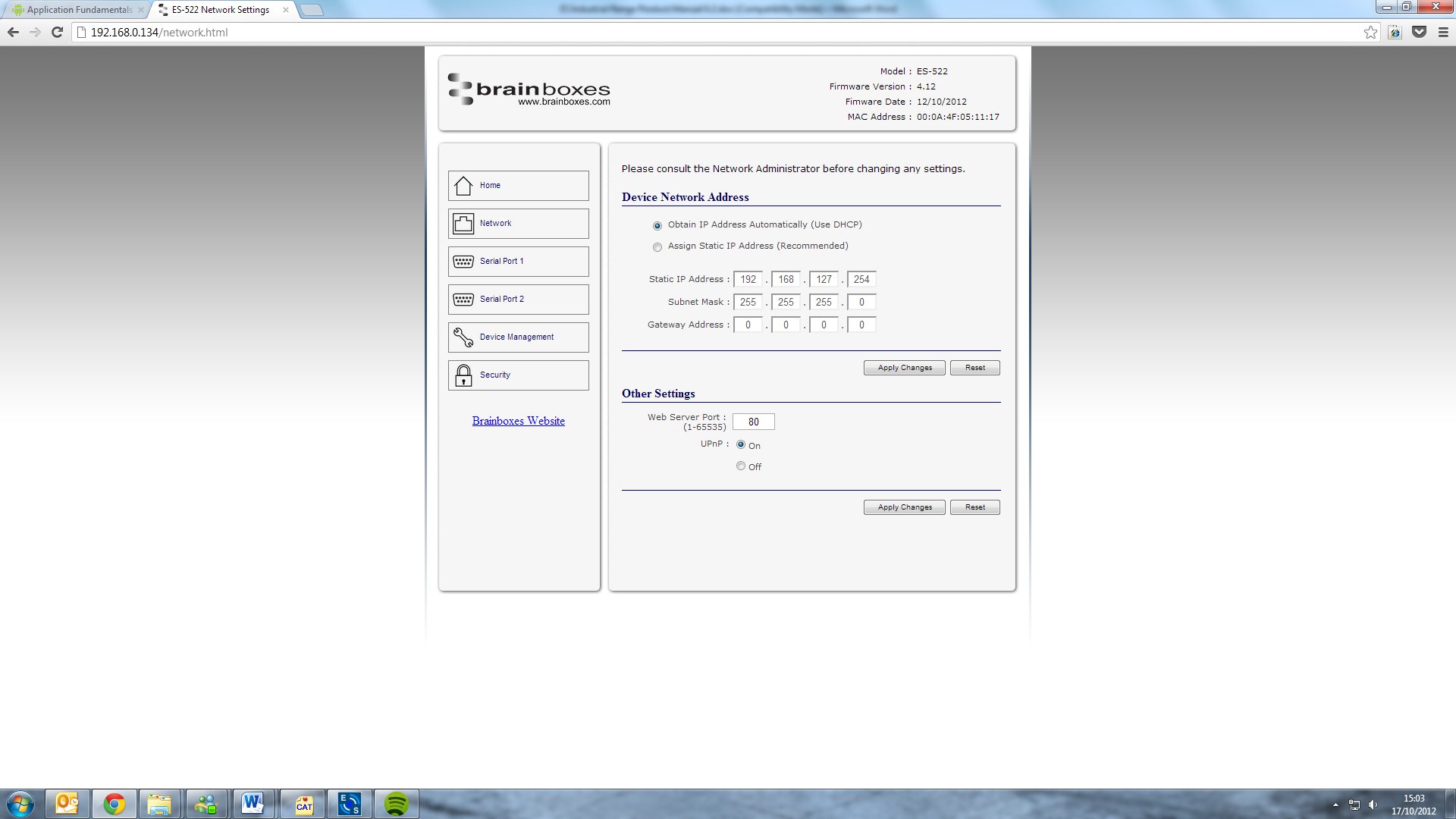
Device Network Address
Here you can change the device's IP address, subnet mask and gateway address. By default the device is set to obtain an IP address automatically by DHCP. If you need the device to use a static IP address, click on the "Assign Static IP Address" radio button, then enter the IP address, subnet mask and gateway into the text boxes. Click "Apply Changes" to save the network address settings.
Other Settings
-
Web Server Port: To change the web server port number, edit the number in Web Server Port box and click the "Apply Changes" button.
-
UPnP: Turning the UPnP of your device off or on can only be done using the web page interface. Turning UPnP off will mean that the ES Device won't be broadcasting on the network. This means you won't be able to find the device using Boost.LAN Manager. You can however add the device manually if you know the IP address and web server port number. If you are using Boost.LAN Manager it is recommended that you install the driver before turning off the UPnP. This will ensure that when Boost.LAN is opened, the installed device will be displayed in the Boost.LAN device manager panel.
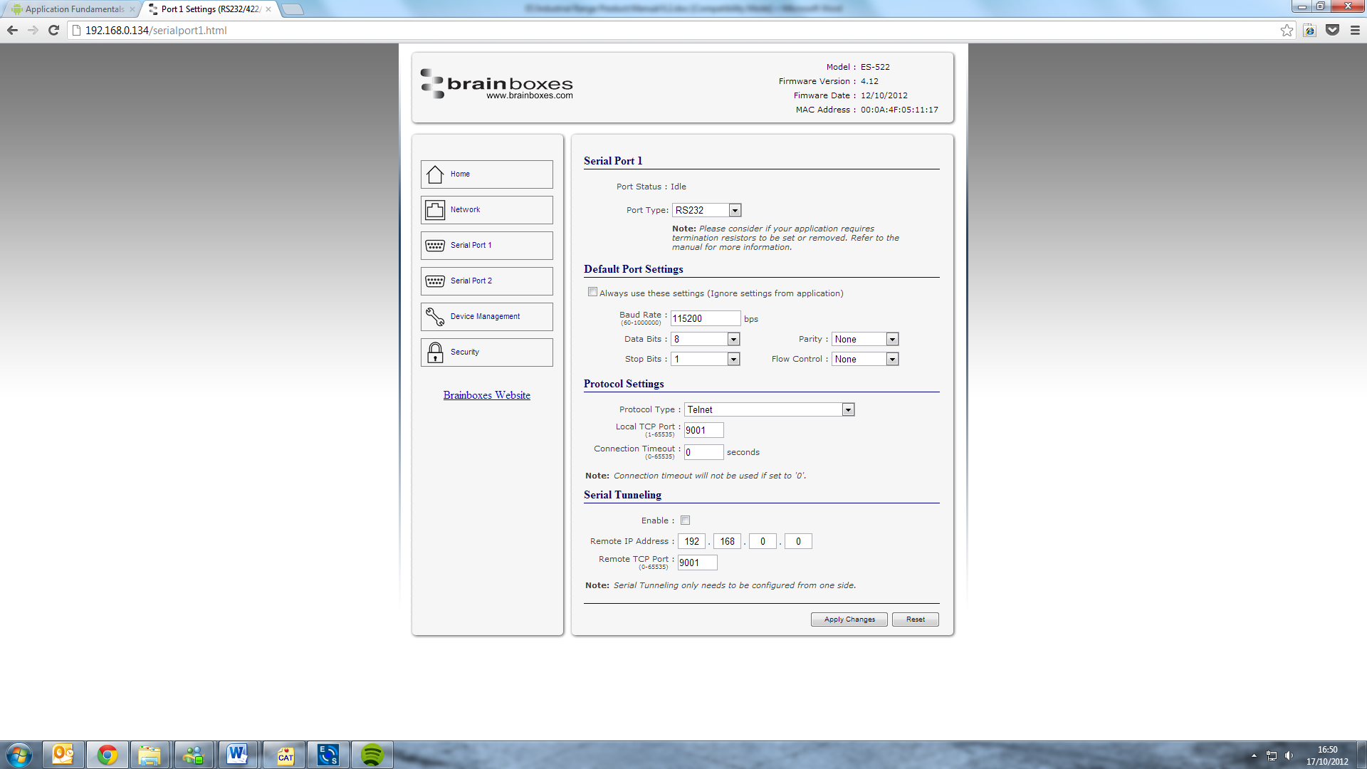
Serial Port Page
-
Port Status: Displays current state of the port, that is, whether the port is open (Connected) or closed (Idle). When the port is connected, the IP address and TCP port the device is connected to is displayed.
-
Port Type: The Port Type drop down box allows you to set the serial port to RS-232 mode or RS-422/485 mode. For information about the pin outs when the port is set to RS-232 or RS-422/485 mode see the Hardware Features section.
-
Always use these settings: If this checkbox is ticked, the port will communicate using the baud rate, data bits, parity, stop bits and flow control set in this section regardless of what settings the application is using. For example, this will allow you to force baud rates that your application does not allow you to select. This can be useful for interfacing to equipment which uses higher baud rates or unusual baud rates which your application does not support.
-
Protocol Settings
- Protocol Type - Raw TCP: Data sent over the network is the same as the data sent over the serial link.
- Protocol Type - Telnet: Data is sent over the Transmission Control Protocol using a virtual terminal connection.
-
Local TCP Port: Configures which TCP port the ES device will use.
-
Connection Timeout: This is set to "0" by default. If the Connection Timeout is set to anything other than 0, the connection to the port will be disconnected automatically after being idle (i.e. no data is being received or sent to and from the port) for the specified time. The LED for the port will go off at this point. If the Connection Timeout setting is "0", the port will need to be disconnected manually by the user.
RS-422/485 Settings
The factory default RS-422/485 setting is full duplex mode.
The RS-485 standard talks about the differential pair as 'Data A' and 'Data B' but line driver chip manufacturers use the labels 'Data+' and 'Data-'.
'Data A' is the inverting pin 'Data-' and 'Data B' is the non-inverting pin 'Data+'
If you can't get the connection to work it may be because you have mistakenly connected the lines the wrong way round.
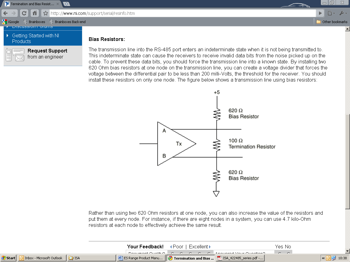
RS-485 Line Failsafe Biasing
Since RS-485 devices have to take turns to send data on the bus there are times when the bus lines are idle, (not driven by any device) and they float to an indeterminate state generating false data.
To solve this; at each end of the RS-485 bus, add a pull up and a pull down resistor to put the line into a known, good state during idle times. Brainboxes products have factory fitted bias resistors that are jumper enabled.
RS-485 Line Termination
Reflections at the end of the twisted pair cable run can interfere with data on the line and so can cause errors.
Brainboxes products have factory fitted termination resistors that are jumper enabled. Fit the jumper ONLY if this device is at the end of the cable.
RS-422 Full Duplex Mode
This mode is generally used between one transmitter / receiver to only one other transmitter / receiver, but it is possible for each output to drive up to 10 receivers.
In RS-422 mode, the ES industrial range of devices have 4 pins, TxD+, TxD-, RxD+ and RxD-. Thus 2 twisted pair cables are used. One twisted pair carries the TxD data outwards, one pair brings the RxD data inward.

The ES-511 has 1 x 6 headers pins for its singular serial port. The ES-522 device has 2 x 6 header pins, one set of 6 per port (2 port device). However the ES-551 and ES-571 have 9 header pins for their singular serial ports. The header pins for T, B- and B+ will control the termination resistors and biasing resistors. For optimum signal quality, fit the T jumper but not the B+ and B- jumpers.
The RS-485 standard is similar to the RS-422 standard upon which it is based. The main difference is that up to 32 transmitter / receiver pairs may be present on the line at one time.
Only one pair of twisted wire cable is used in RS-485 Half Duplex communication, Data+ and Data-.
These are the two main wiring schemes:
- RS-485 One Talker Many Listeners (Half Duplex)
- RS-485 Many Talkers Many Listeners (Half Duplex)
Half-duplex links usually need biasing resistors fitted at some point on the link. These resistors are used to hold the signal lines in a known state when the transmitters are off. If these resistors aren't used it is likely that random data will be received when no transmitter is turned on. This is because of noise which is picked up along the cable which causes the lines to float to unknown states. The B+ resistor pulls the '+' line up to 3V3 and the B- resistor pulls the other '-' line down to ground.
It doesn't matter which device on the link has them, as long as one of them does. Biasing resistors can be connected by fitting the B+ and B- jumpers onto the headers on the ES device PCB.
The T jumper connects in a termination resistor. Termination resistors are used on the end devices in the link to absorb the signal and stop echoes of the data being reflected back onto the transmission line.
For point-to-point links (two devices linked), this should be fitted for both devices. For a multi-drop bus (more than two devices linked on the same cable), the termination should be present at the two end devices but not at any of the devices in between.
To access the headers, the case of the ES device needs to be opened.
Jumpers can be placed vertically across any of the 3 sets of pins explained as thus below:
- B+ and B- = are bias resistors
- T = Termination resistor
- PARK = disabled both biasing and terminating resistors
So the possible configurations are:

Half-duplex point-to-point link, when no other biasing is present and when biasing is already present somewhere.
For a half-duplex multi-drop bus, if the device is at the end of the bus then use the same jumper configurations as for a half-duplex point-to-point link, above.


For a half-duplex multi-drop bus, where the device is not at the end of the bus but somewhere in the middle. Or depending on whether biasing is already presented somewhere.
Serial Tunnelling
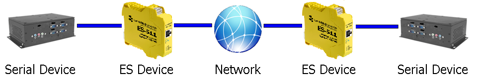
Brainboxes Ethernet to Serial industrial devices have a feature called serial tunnelling. Serial tunnelling connects two devices together to create a serial tunnel which extends the serial link over an Ethernet connection. When serial data is sent, it is converted to Ethernet packets by one ES industrial device, transmitted over the network, then unpacked and converted back to serial data by the other ES industrial device. An example of tunnelling is shown in the diagram below.
Serial tunnelling is set up using the webpage interface. In the following instructions there are two devices which are referred to, the local side which is the device that you are connecting from, and the remote side which is the device you are connecting to.
-
Open the web configuration page of the Local ES Device using a web browser.
-
Navigate to the page of the serial port you want to use to tunnel.
-
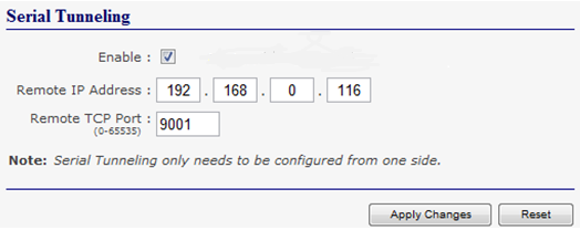
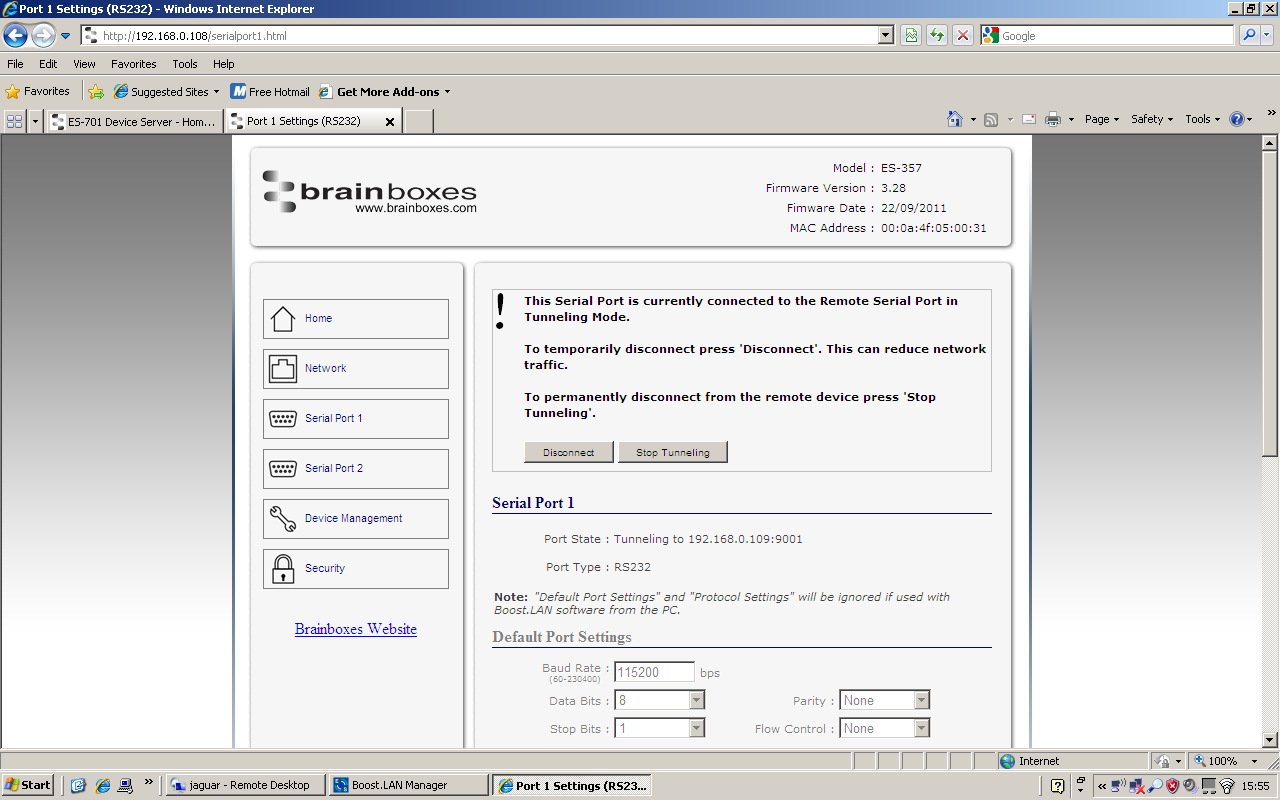
At the bottom of this web page is the device tunnelling section.
-
To connect tunnelling tick the "Enable" checkbox and select if you want the device to be master or slave. Enter the Remote IP Address and Remote TCP Port number of the ES device you want to connect to and tick the 'Enable' check box.
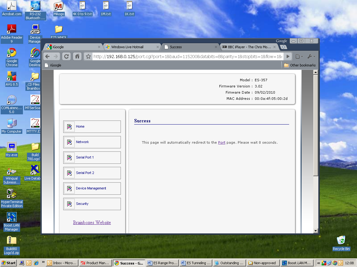
- Click 'Apply Changes' button and you will be taken to a page which will display a success page. You will be redirected to the port page after the countdown timer has finished.
-
The devices will now be in tunnelling mode.
-
On the local device port webpage you will see the device tunnelling section with two buttons, 'Disconnect' and 'Stop Tunnelling'. The 'Stop Tunnelling' button will disconnect the ports on the remote and local side and put both of the devices to an idle state. If the 'Disconnect' button is clicked the remote side port will be disconnected and go into the idle state, but the local side will remain in tunnelling mode.
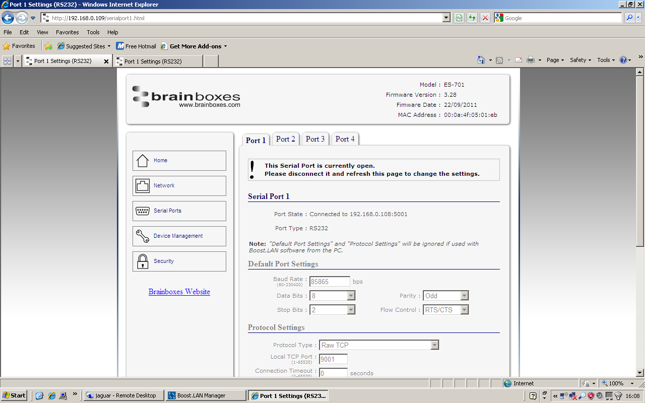
- On the remote device web configuration page, the Serial port that is tunnelling will show that the port is connected.
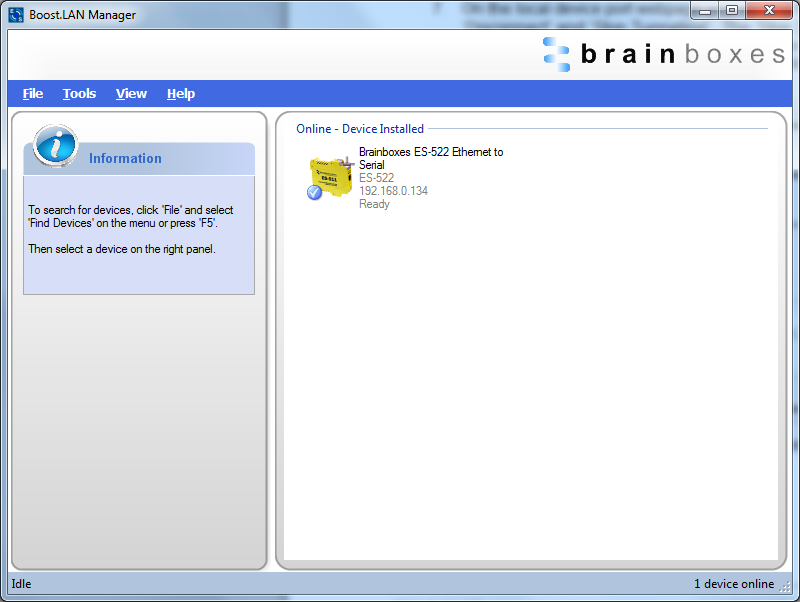
- In Boost.LAN Manager, the symbol in the image below will be displayed when a device in is connected in tunnelling mode.
Device Management
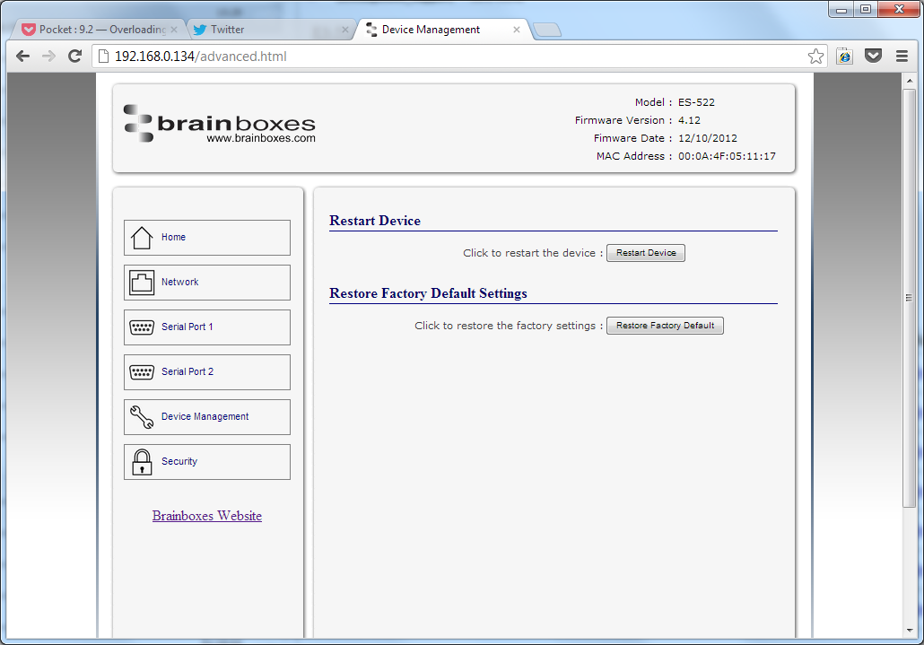
On the device management page there are two options. The first to restart the device and the second to restore the device to factory settings. Before clicking either of the buttons make sure that the device is not in use.
-
Restart Device: Clicking this button will reboot the device while keeping all the devices settings.
-
Restore Factory Default: Restoring the factory default will revert all the settings of the device back to the factory defaults and then reboot the device.
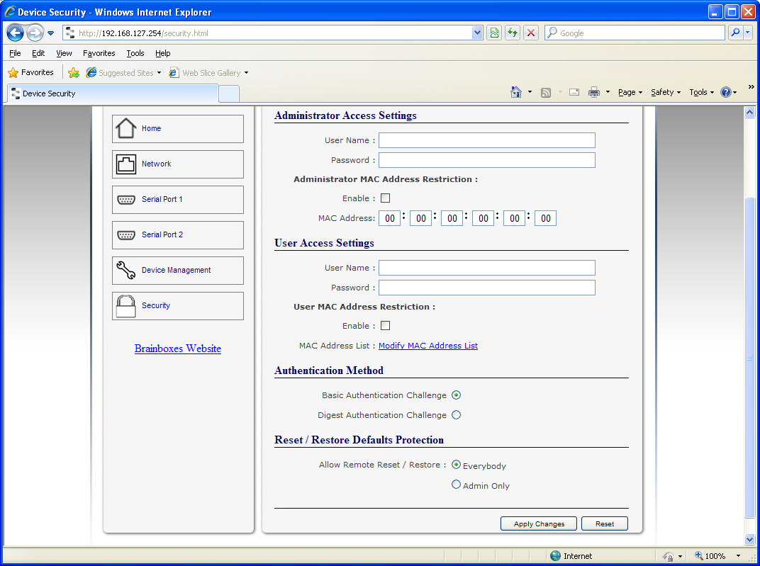
Security
Anyone with access to the network can access the webpage of your ES device and change its settings. To prevent this from occurring, there are security features available on the device that can restrict access to certain web pages to account holders only.
Administrator Access Settings
Creating an Administrator account restricts access to the Security Page to the Administrator account holder. All other pages are still accessible to other users.
To create an Administrator account:
-
Open the device's Webpage by typing the device's IP address into a browser
-
On the left hand menu, click Security. This will open the device's Security Settings page.
-
Enter a username and password in the "Administrator Access Settings" section
-
Click "Apply Changes" at the bottom of the page.
-
To access the security page of the device via the webpage again, you will be prompted with a log in prompt. Only the administrator will have access to this page.
User Access Settings
Creating a User Access account restricts complete access to the web page interface of your device to a User Account or Administrator account holder. No configuration page can be accessed without logging in using the user or administrator log on credentials.
- A User account may be created without an Administrator account.
- Both an Administrator and User Account can be set up on the same device. If both are setup, the Security Page will be restricted to the Administrator account holder only. If just a User is setup, then the User has access to all areas.
To create a User account:
-
Open the device's Webpage by typing the device's IP address into a browser.
-
On the left hand panel, click Security. This will open the device's Security Settings page.
-
Enter a username and password in the "User Access Settings" section.
-
Click "Apply Changes" at the bottom of the page.
-
To access the web interface of the device again, you will be prompted with a log in prompt. Only an administrator or user will be able to log in.
MAC Address restriction
In addition to Administrator and User accounts to restrict access to users with the correct log on credentials, there is a feature called "MAC address restriction"
- MAC address restriction is available under both Administrator and User settings.
- Enabling MAC address restriction means access that the device will be limited to Administrators or Users with the MAC addresses specified in the MAC Address list. For example:
- The Administrator/User is expected to always log in from the same MAC address. Even if the correct username and password are entered, access will be refused if the MAC address is different.
WinSock and UPnP communications are also restricted to specified MAC addresses.
-
Administrators are automatically Users, so there is no need to add the Administrator MAC address to the User MAC address list.
-
With MAC address restriction enabled, the device will only appear visible on specified MAC addresses.
Restricting "Reset/Restore Default"
Once an Administrator account is set up, access to the "Device Management" page to "Reset or Restore Default settings" is still available to all users. Alternatively, if both an Administrator and User are set up, both the Administrator and User can access the page.
To avoid any unauthorised "Resetting or Restoring to Default", the following features are available:
- Everybody: This will restrict the ability to reset or restore to those with an administrator or user account
- Admin only: This will restrict the ability to reset or restore to the administrator only.
You must set up an Administrator account or a User account (or both depending on requirements) for "Reset/Restore Defaults Protection" to take effect.
Authentication Method
There are two authentication methods:
-
Basic Authentication Challenge: Log on credentials are passed as plaintext over the network.
-
Digest Authentication Challenge: Log on credentials are encrypted when sending over the network and as such, more secure than Basic Authentication Challenge.