
ES Industrial Hardware Features
Technical Specifications
Network connection
- 10Base-T or 100Base-TX Ethernet connection
- Standard 8P8C ("RJ45") socket connector
- TCP/IP protocol stack
- DHCP or static IP address
- Automatic transmit/receive crossover detection
- 1500V magnetic isolation
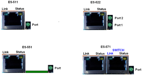
The ES-522 has 2x serial ports: port 1 is coloured as yellow and port 2 is coloured as grey.
RS-232 Serial Port
- Baud rates up to 1M Baud
- 5, 6, 7 or 8 data bits
- 1, 1.5 or 2 stop bits
- Odd, even, mark, space or no parity bit
- Line-break generation and detection
- RTS/CTS or XON/XOFF flow control option
- ESD protection to 15kV human body model
- Can be connected to as a Windows COM port, as a Raw TCP socket, or using the RFC2217 standard
- Serial cable length: 10m / 30 feet maximum
RS-422/485 Full Duplex Serial Port
The factory default setting for the ES devices is RS-422 full duplex.
Background Information:
DTR/DSR and CTS/RTS Handshaking is not available.
This mode is generally used between one transmitter / receiver to only one other transmitter / receiver, but it is possible for each output to drive up to 10 receivers.
Generally, in RS-422 systems, all 4 signal lines from the 5 pin terminal block participate in the data transfer sequence. Thus 2 twisted pair cables are used. One twisted pair carries the TXD data outwards, one pair brings the RXD data inward.
- Baud rates up to 1M Baud
- 5, 6, 7 or 8 data bits
- 1, 1.5 or 2 stop bits
- Odd, even, mark, space or no parity bit
- Line-break generation and detection
- XON/XOFF flow control option
- Built-in termination and biasing at receiver inputs
- Can be connected to as a Windows COM port, as a Raw TCP socket, or using the RFC2217 standard
- Serial cable length: 1200 meters / 4000 feet maximum
RS-422/485 Half Duplex Serial Port
- Baud rates up to 1M Baud
- 5, 6, 7 or 8 data bits
- 1, 1.5 or 2 stop bits
- Odd, even, mark, space or no parity bit
- Line-break generation and detection
- Automatic switching between transmit and receive states in half-duplex mode
- 2-wire half-duplex RS-422/485 link mode
- Built-in termination and biasing at receiver inputs
- Can be connected to as a Windows COM port, as a Raw TCP socket, or using the RFC2217 standard
- Serial cable length: 1200 meters / 4000 feet maximum
Power
- Wide-range +5 to +30V DC 60mA@24V 1.4W Typical 120mA@24V 2.9W Max
- Reverse voltage protected
- ESD and surge protected
- Earthing connection point
LED indicators
LED Indicators for the network and serial ports show when a connection is open and when data is being transferred. A two-colour status LED provides additional information on the status of the device.
Terminal Block Connector Pin out
| Pin 1 | Pin 2 | Pin 3 | Pin 4 | Pin 5 | |
|---|---|---|---|---|---|
| RS-232 | Sig GND | CTS | RxD | RTS | TxD |
| RS-485 FD | Sig GND | RxD- | RxD+ | TxD+ | TxD- |
| RS-485 HD | Sig GND | Data+ | Data- | ||
| Power Input | Power GND | +Vin A | +Vin B | Power GND | Func GND* |
A second power supply +VinB can be fitted as a back-up to the main power supply +VinA to prevent down time should one power source fail.
*Func Ground - Functional ground is a connection to the ground from the DIN rail.
Header pins and jumper settings
To access the headers, the case of the ES device needs to be opened.
Jumpers can be placed horizontally across any of the 3 sets of pins explained as thus below:
- B+ and B- = are bias resistors
- T = Termination resistor
- PARK = disables both bias and terminating resistors


By default the biasing jumpers (B+ and B-) and terminating resistor (T) are set in the ON position. If the jumpers are in the PARK position, then the biasing and termination resistor are disabled.
Reset Button
Manual Reboot
- Press the reset button once.
- The status LED will flash and after 5 seconds the device will reboot.
- When the device is restarted, any connections you have had to the COM ports will need to be re-established.
Manual Hard Restore
- Press and hold the reset button on the device for 5 seconds.
- The status LED will flash red/green and the device will be restored to factory default settings. For the factory settings, see the Factory Default Settings section below.
Storage and Operating Environment Guidelines
| Parameter | Range |
|---|---|
| Operating Temperature | -30°C to +80°C |
| Storage Temperature | -50°C to +150°C |
| Humidity | 5% to 95% non-condensing |
| Housing | IP-30 rated non-conducting polyamide case with integrated DIN rail mount |
Factory Default Settings
Network Settings
| Setting | Default Value |
|---|---|
| Device Network IP Address | DHCP Mode |
| Web Server Port | 80 |
Port Settings
| Setting | Default Value |
|---|---|
| Port Mode | RS-422 |
| Baud rate | 115200 |
| Databits | 8 |
| Stop bits | N |
| Parity | 1 |
| Flow Control | None |
| Duplex mode | Full Duplex |
| Protocol Settings | Telnet Mode (Server) |
The default settings have been carefully selected and should provide the right settings for the majority of users.
Device Swapping
In the unlikely event of a device failing, it can be easily replaced by swapping it with a device which has the same IP address. This is particularly useful when using a large number of ES industrial devices together which have already been installed and setup and are already communicating with peripherals. The faulty device can be replaced without having to set up and install a new device.
One of the features of Boost.LAN Manager is the ability to export and import device settings. This feature is particularly useful if you are swapping devices. The old device's settings can be exported into a settings file and then imported on the new device. For details on how to use this feature see Exporting and Importing Device Settings.