
ES Light-Industrial RS-422/485 Settings
RS-422/485 Settings (ES-320/ES-313/ES-346/ES-842/ES-357/ES-031/ES-042/ES-420/ES-413)
The factory default setting for the ES devices is RS-422 full duplex.
DTR/DSR Handshaking is not available on 422/485 ports.
The RS-485 standard talks about the differential pair as 'Data A' and 'Data B' but line driver chip manufacturers use the labels 'Data+' and 'Data-'. 'Data A' is the inverting pin 'Data-' and 'Data B' is the non-inverting pin 'Data+'
If you can't get the connection to work it may be because you have mistakenly connected the lines the wrong way round.
The RS-422 Standard
The RS-422 standard defines a serial communications standard. RS-422 is a high speed and/or long distance data transmission. Each signal is carried by a pair of wires and is thus a differential data transmission system. Over distances up to 40 feet the maximum data rate is 10 Megabits per second, and for distances up to 4000 feet the maximum data rate is 100 Kilobytes per second. A 120-Ohm resistor should be used to terminate the receiving end of the line. It is generally used between one transmitter receiver pair to ONLY one other transmitter receiver pair, but each output can drive up to 10 receivers.
| RS-422 Standard - 1 Driver up to 10 Receivers | |---|---| | Line Length | Max Data Rate | | 40 Feet = 12m | 10 Mbits/sec | | 400 Feet = 122m | 1 Mbits/sec | | 4000 Feet = 1219m | 100 Kbits/sec |

RS-422 Operation
Generally, in RS-422 systems all 8 signal lines from the 9 pin D connector participate in the data transfer sequence, thus 4 twisted pair cables are used. One twisted pair carries the TXD data outwards, one pair brings the RXD data inward, another pair carries the RTS handshake outwards and the fourth pair brings the CTS handshake inwards. There is no need to carry the ground from one device to another. This RS-422 arrangement allows data to be transmitted and received simultaneously since each signal has its own data cable pair. In addition, the receiver can set RTS true so telling the transmitter on its CTS input that the receiver is ready to accept data. In this way, no data will ever be transmitted when the receiver is unable to accept it, due to a full input buffer etc. And so no data will be lost.
RS-422 Full Duplex Mode
This mode is generally used between one transmitter / receiver to only one other transmitter / receiver, but it is possible for each output to drive up to 10 receivers.
Generally, in RS-422 systems, all 8 signal lines from the 9 pin D connector or terminal block participate in the data transfer sequence. Thus 4 twisted pair cables are used. One twisted pair carries the TXD data outwards, one pair brings the RXD data inward, another pair carries the RTS handshaking signal outwards, and the fourth pair brings the CTS handshaking signal inwards. There is no need to carry the ground from one device to another.
RS-485 Standard
The RS-485 standard is similar to the RS-422 standard upon which it is based. The main difference is that up to 32 transmitter / receiver pairs may be present on the line at one time.
Generally not all the lines available on the 9 pin D connector or terminal block are used for RS-485 systems. The RTS+/- and CTS+/- lines, though driven by the device, are usually not connected. In two wire Half-Duplex configuration, the TXD+ line is connected to RXD+, whilst the TXD- line is connected to RXD-. Only one pair of twisted wire cable is used in RS-485 Half Duplex communication.
| RS-485 Standard - Up to 32 Driver/Receiver Pairs | |---|---| | Line Length | Max Data Rate | | 40 Feet = 12m | 10 Mbits/sec | | 400 Feet = 122m | 1 Mbits/sec | | 4000 Feet = 1219m | 100 Kbits/sec |

RS-485 Operation
The RS-485 standard is intended for up to 32 driver receiver pairs on the bus. The line drivers used in the RS-422/485 card are designed to work correctly in both RS-422 and RS-485 systems. The main difference therefore is in how the system is implemented. Though the card uses a 9 pin D connector, in general, not all the lines are used for RS-485 systems. The RTS+/- and CTS+/- lines, though driven by the card, are usually not connected. In two wire, Half-Duplex configurations the TXD+ line is connected to the RXD+ whilst the TXD- line is connected to the RXD-, only one pair of twisted wire cable is used in RS-485 Half Duplex communications. The hardware handshaking performed by the CTS+/- and RTS+/- lines in RS-422 systems are handled by a software protocol in RS-485 systems. In situations where more than one device may transmit data on the shared data line, each cards RTS line is used as a gating signal to enable the TXD driver only when that card needs to transmit data. This mechanism prevents bus contention caused by multiple transmitters holding the line in opposing states. Our cards have a facility which automatically "gates" the RTS line, thus enabling the transmitter independently of any software. The three wiring schemes given described below are:
- RS-485 One Talker Many Listeners (HALF DUPLEX)
- RS-485 Many Talkers Many Listeners (HALF DUPLEX.)
- RS-485 Many Talkers Many Listeners (FULL DUPLEX.)
RS-485 One Talker - Many Listeners, Half Duplex
There are several schemes for connecting RS-485 devices depending on the characteristics of the system. In many cases there will be only one device, which can transmit, data and all the others simply listen to it. This scheme is used for theatrical lighting intensity control in the DMX512 standard. This is shown below. There is NO multiplexing of the TXD and RXD lines. Data is only flowing one way, from PC outwards, and is thus a Half-Duplex configuration; only one twisted pair cable is needed.

The Receiver end of MAIN line terminated in characteristic impedance by ONBOARD resistor networks stubs off the main not terminated. In the above scheme, one RS-485 device is talk only, it transmits data, but it does not receive any. The other RS-485 devices are received only; they do not transmit any data at all.
RS-485 Many Talkers - Many Listeners, Half Duplex
Another popular RS-485 layout is for multiple talkers and multiple listeners. This is shown below. This is also known as "party line" transmission. It is imperative to have some method of preventing two devices trying to drive the data lines at the same time. The normal method is to use the RTS line as a talk enable. The RTS line should go true immediately prior to the data transmission and go false immediately after the last byte in the stream is sent.
BOTH ends of MAIN line terminated in characteristic impedance, stubs off main line not impedance, since both ends receive. The twisted pair ends are wired to both RXD+ & TXD+ and RXD- & TXD- at each RS-485 device!
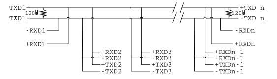
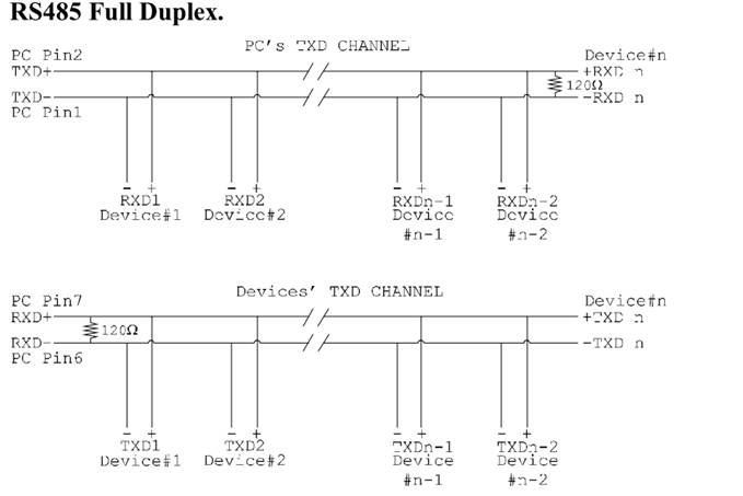
RS-485 Many Talkers - Many Listeners, Full Duplex
The RS-485 many talkers, many listeners, Full Duplex system can be used when all the RS-485 devices have separate Transmit and Receive channels. There is NO multiplexing of the TXD and RXD signals on the same device. This system is especially useful when there is no flow control available on the PC, usually due to the use of a third party communications program that prevents the use of the RTS signal as a "transmit enable" control. It can be used in the following situations:
a) The PC is connected to only ONE RS-485 device.
b) The PC is communicating with several RS-485 devices that are each able to recognize and respond to their own unique address. The RS-485 devices only drive their TXD lines when they are responding to requests from the PC to send data. In effect, the RS-485 device's address and the command it receives is used to control access to the devices TXD channel.
This is a Full Duplex system. Two twisted pair cables are required. One twisted pair, is the PC's TXD channel, it carries the data sent from the PC's TXD outputs to the RXD inputs of each of the RS-485 devices. The second twisted pair, is the Devices TXD channel, it carries the data sent from each of the devices' TXD outputs to the RXD inputs of the PC. The advantages of this system are great, since no new communications, software is needed, and the PC can talk and listen at the same time. In effect, the handshaking is performed by the intelligence of the RS-485 devices attached to the PC. When wired as below, the PC can transmit data at any time and all the RS-485 devices #1 to #n simultaneously receive it. Only one of the RS-485 devices may talk, i.e. transmit data, at any one time. Each RS-485 device recognizes commands and data addressed to it; it only talks when the PC commands it to do so. When the RS-485 device receives the command to talk from the PC, it gates its TXD drivers on, sends the data down the device TXD channel, and disables its TXD drivers. The other RS-485 devices remain in the 'receive only' mode when they are not being addressed, they do not transmit any data at all.
RS-422 Serial Port Cables
Use screened twisted pair Belden cable 9729 and 9829, L type 2493 and 2919 cable to make the RS-422 connection. Unscreened Belden type 8795 may also be used in less noisy environments. The on board resistor networks terminate the receiving end of the twisted pair cable in its characteristic impedance.
RS-485 Serial Port Cables
For best noise immunity use twisted pair cables to make the RS-485 connection. In Half Duplex wiring only 1 twisted cable pair is needed. Two twisted pair cables are needed for Full Duplex communications. Use screened twisted pair Belden cable 9729 and 9829, UL type 2493 and 2919 cable to make the RS-485 connection. Terminate the twisted pair cable.
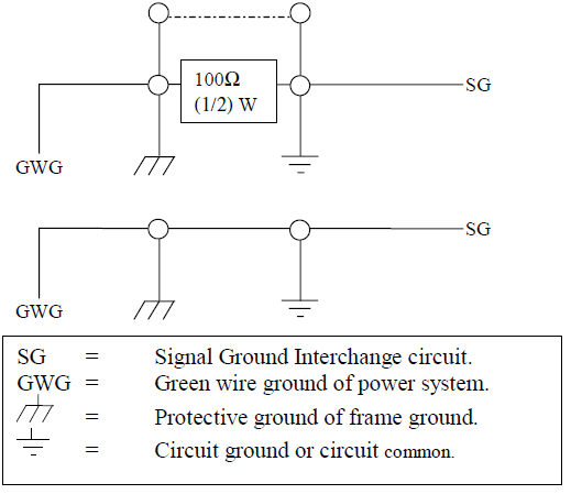
Optional Grounding Arrangements
Proper operation of the cable circuit, according to TIA EIA: 485 A (1995) requires that the cable ground shield is not connected directly to the equipment ground shield. A current limiting resistor should be used in series with the shield to avoid possible large current flow due to differences in ground potential. Any one of the methods shown below can do this.
The circuit common of the equipment is connected to protective ground, at one point only by a 100 Ohm, +/-20% resistor with a power dissipation rating of 1/2W. An additional provision may be made for the resistor to be bypassed with a strap to connect signal common and protective ground directly together when specific installation conditions necessitate.
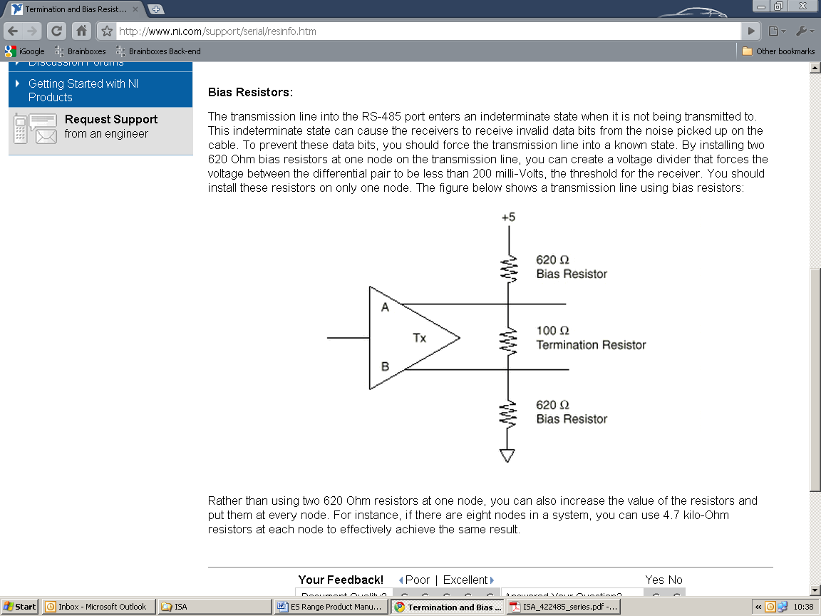
RS-485 Line Failsafe Biasing
Since RS-485 devices have to take turns to send data on the bus there are times when the bus lines are idle, (not driven by any device) and they float to an indeterminate state generating false data. To solve this; at each end of the RS-485 bus, add a pull up and a pull down resistor to put the line into a known, good state during idle times. Brainboxes products have factory fitted bias resistors that are jumper enabled.
RS-485 Line Termination
Reflections at the end of the twisted pair cable run can interfere with data on the line and so can cause errors.
Brainboxes products have factory fitted termination resistors that are jumper enabled. Fit the jumper ONLY if this device is at the end of the cable.
These are the two main wiring schemes:
- RS-485 One Talker Many Listeners (Half Duplex)
- RS-485 Many Talkers Many Listeners (Half Duplex)
Please see the Technical Specifications for the pin outs of RS-422 and RS-485 for your ES Device.
RS-485 Full Duplex Mode (ES-313, ES-320, ES-346 & ES-842)
This mode is generally used between one transmitter and many receivers. It uses 2 twisted pair cables, one carries the TXD data outwards and one brings the RXD data inward.
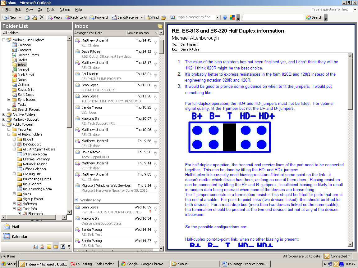
For full-duplex operation, the HD+ and HD- jumpers must not be fitted. For optimal signal quality, fit the T jumper but not the B+ and B- jumpers.
RS-485 Full Duplex (ES-357)
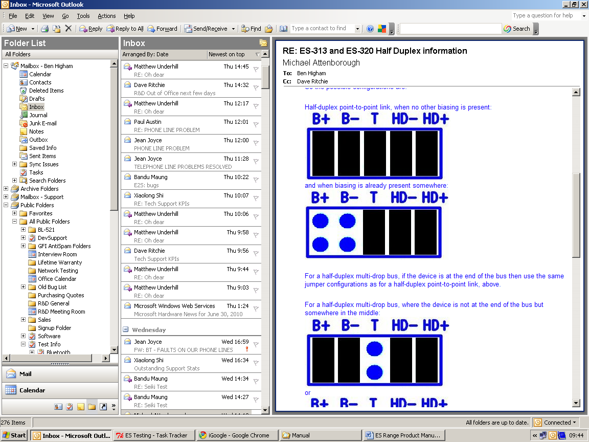
To set the ES-357 to full duplex mode, this needs to be done by changing the settings for the COM port. To open RS-422/485 settings:
- Double click the port entry in Boost.LAN Manager
- Go to the Port Settings tab
- Click Advanced
- Go to the RS-422/485 Settings tab.
- The drop down list allows users to choose the desired RS-422/485 operations mode.
- Select "RS-422 full duplex mode" for Full Duplex communications.
Pressing the "Restore Defaults" button will reset all settings on this Property Page back to the factory defaults of this device. The default settings for this Property Page are "RS-422 full duplex mode".
RS-485 Half Duplex Autogating Mode (ES-357 Only)
For the RS-422/485 port on the ES-357, there is an additional tab in the Advanced Settings of the Windows COM port to allow you to change duplex mode to half duplex autogating mode. The factory default setting is RS-422 full-duplex mode.
When the duplex mode is set to half duplex autogating the ES device will automatically detect the start of the PC's transmissions and will gate the PC's transmitter onto the twisted pair cable. It will then automatically detect the stop bit being sent and gates the port off the twisted pair cable.
To open RS-422/485 settings:
- Double click the port entry in Boost.LAN Manager
- Go to the Port Settings tab
- Click Advanced
- Go to the RS-422/485 Settings tab.
- The drop down list allows users to choose the desired RS-422/485 operations mode.
- Select "RS-422 full duplex mode" for Full Duplex communications.
- Select "RS-485 half duplex autogating mode" for Half Duplex communications.
Pressing the "Restore Defaults" button will reset all settings on this Property Page back to the factory defaults of this device. The default settings for this Property Page are "RS-422 full duplex mode".
RS-485 Half Duplex Mode (ES-313, ES-320, ES-346, ES-842, ES-420 & ES-413 only)
For half-duplex operation, the transmit and receive lines of the port need to be connected together making it a 2 wire system. This can be done by fitting the HD+ and HD- jumpers onto the headers inside the ES device box.
Half-duplex links usually need biasing resistors fitted at some point on the link. These resistors are used to hold the signal lines in a known state when the transmitters are off. If these resistors aren't used it is likely that random data will be received when no transmitter is turned on. This is because of noise which is picked up along the cable which causes the lines to float to unknown states. The B+ resistor pulls the '+' line up to 3V3 and the B- resistor pulls the other '-' line down to ground.
It doesn't matter which device on the link has them, as long as one of them does. Biasing resistors can be connected by fitting the B+ and B- jumpers onto the headers on the ES device PCB.
The T jumper connects in a termination resistor. Termination resistors are used on the end devices in the link to absorb the signal and stop echoes of the data being reflected back onto the transmission line.
For point-to-point links (two devices linked), this should be fitted for both devices. For a multi-drop bus (more than two devices linked on the same cable), the termination should be present at the two end devices but not at any of the devices in between.
To access the headers, the case of the ES-313 or ES-320 needs to be opened.
Jumpers can be placed vertically across any of the 5 sets of pins explained as thus below:
- B+ and B- = are bias resistors.
- T = Termination resistor
- HD+ and HD- = are half duplex pins.
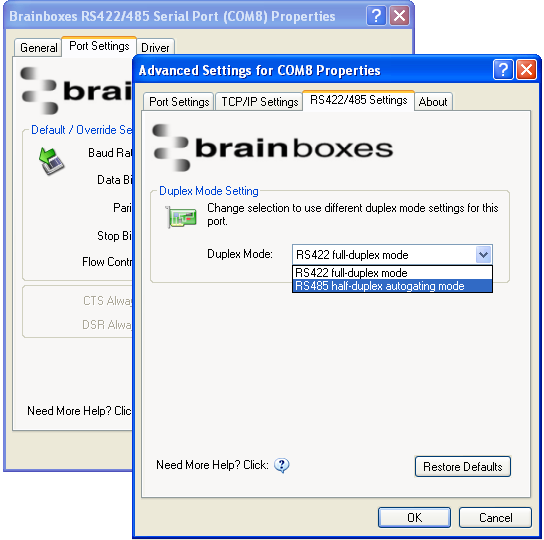
So the possible configurations are:
Half-duplex point-to-point link, when no other biasing is present.
And when biasing is already present somewhere.
For a half-duplex multi-drop bus, if the device is at the end of the bus then use the same jumper configurations as for a half-duplex point-to-point link, above.
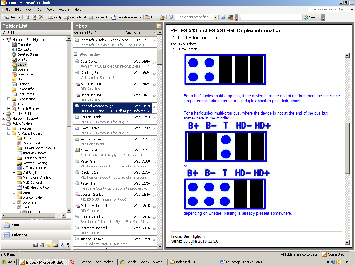
For a half-duplex multi-drop bus, where the device is not at the end of the bus but somewhere in the middle.
Or depending on whether biasing is already presents somewhere.