ES Light-Industrial Advanced Configuration
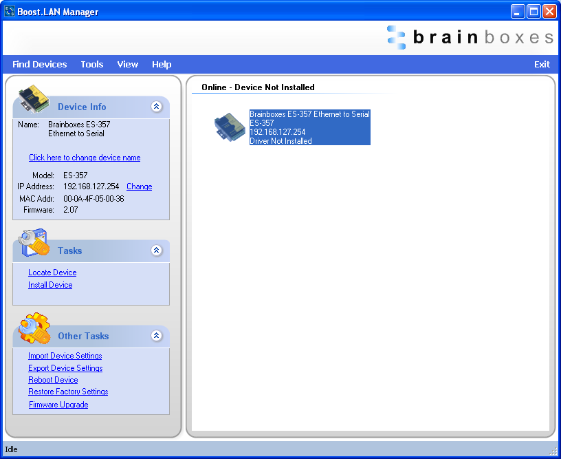
ES devices store the device settings inside the device. When you access the webpage it gets these settings from the device. When you access the driver it gets the settings from the device too. If you have Boost.LAN closed and change a setting on the webpage, the device driver will not know that the settings have been changed on the webpage until Boost.LAN is opened. When Boost.LAN first opens it will update the settings of any installed devices. Therefore you need to open Boost.LAN manager after changing a setting on the webpage in order for the driver to use this new setting.
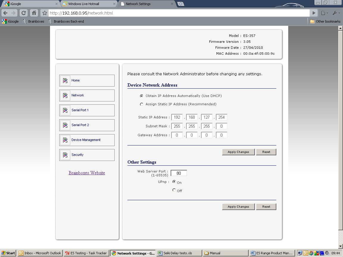
IP Addressing
The IP settings can be easily changed by clicking the "Change" link available in the "Device Info" section on the left hand panel of Boost.LAN Manager.
This will bring up the following dialogue box.
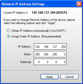
As mentioned in the "Features" section of this manual, the ES device is shipped in DHCP Mode. On connecting to the network, the device automatically checks if it is connected to a DHCP Server. If this is the case, the DHCP server will allocate an IP address automatically to the ES device.
If no DHCP Server is detected within 60 seconds (e.g. you are using a direct cable connection to the PC), the ES device will default to the IP address specified in the static IP Settings as shown above. By default, this is 192.168.127.254.
Port Settings
The Port Settings allow you to set Default or Override Settings for the serial communication and how to deal with incoming hardware handshaking events.
To open 'Port Settings', open Boost.LAN Manager and Double Click on the Brainboxes COM Port Entry.
Then Click on the 'Port Settings' tab.
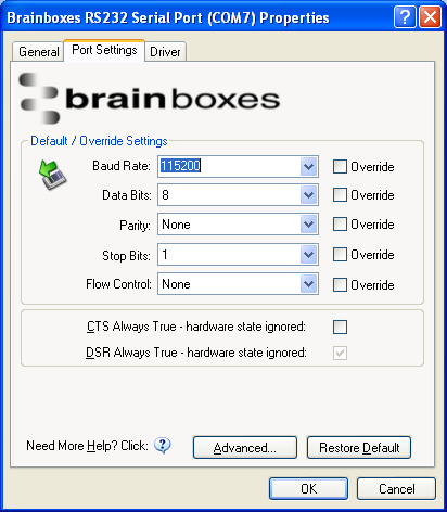
All options can be selected from the Dropdown Menus. In addition, you can enter a non-standard value into the Baud rate
Once the desired settings have been achieved, you must click OK to activate them. At any time click the 'Restore Default' button to return to the original setup.
Default / Override Settings
Default Settings will be set if an application does not specify the serial settings when it opens the COM Port.
- This is sometimes the case with old Legacy applications and you will need to choose these settings to match the communications that you wish to use.
- The majority of Applications will specify what Serial Settings they wish to use. In this case, it will not matter what the Default settings are, as the Port will be opened with the Application's Settings.
When the 'Override' box is checked next to the Default Setting, the Port will communicate at this setting whether an application has requested it or not.
- For example, this will enable you to force baud rates that your application does not allow you to select. This can be useful for interfacing to equipment which uses higher baud rates or unusual baud rates, which your application does not support.
- In a case where you want to use hardware handshaking, but your application is not capable, you can select CTS Always True - Hardware state ignored and choose to Override it.
With the use of Override Settings, you need to ensure that the equipment you are connecting to be setup to match the communications settings you are forcing.
CTS / DSR Always True
CTS and DSR are incoming hardware handshaking lines. This means they receive signals from the connected device which tell the Ethernet to Serial device when it is and isn't OK to send data.
Sometimes these signals may want to be ignored. By forcing CTS or DSR True, the Ethernet to Serial device will ignore those signals and always send data.
These settings are especially helpful when CTS and DSR are not physically connected (such as in a 3 wire setup) and it is not acceptable for the data flow to stop and start due to arbitrary variances on the unconnected signal lines.
Some ES devices do not support RTS/CTS or DTR/DSR handshaking and as a result, "CTS Always true" or "DSR Always true" will be enabled by default. Please check the product datasheet for your device to see what hardware handshaking is available.
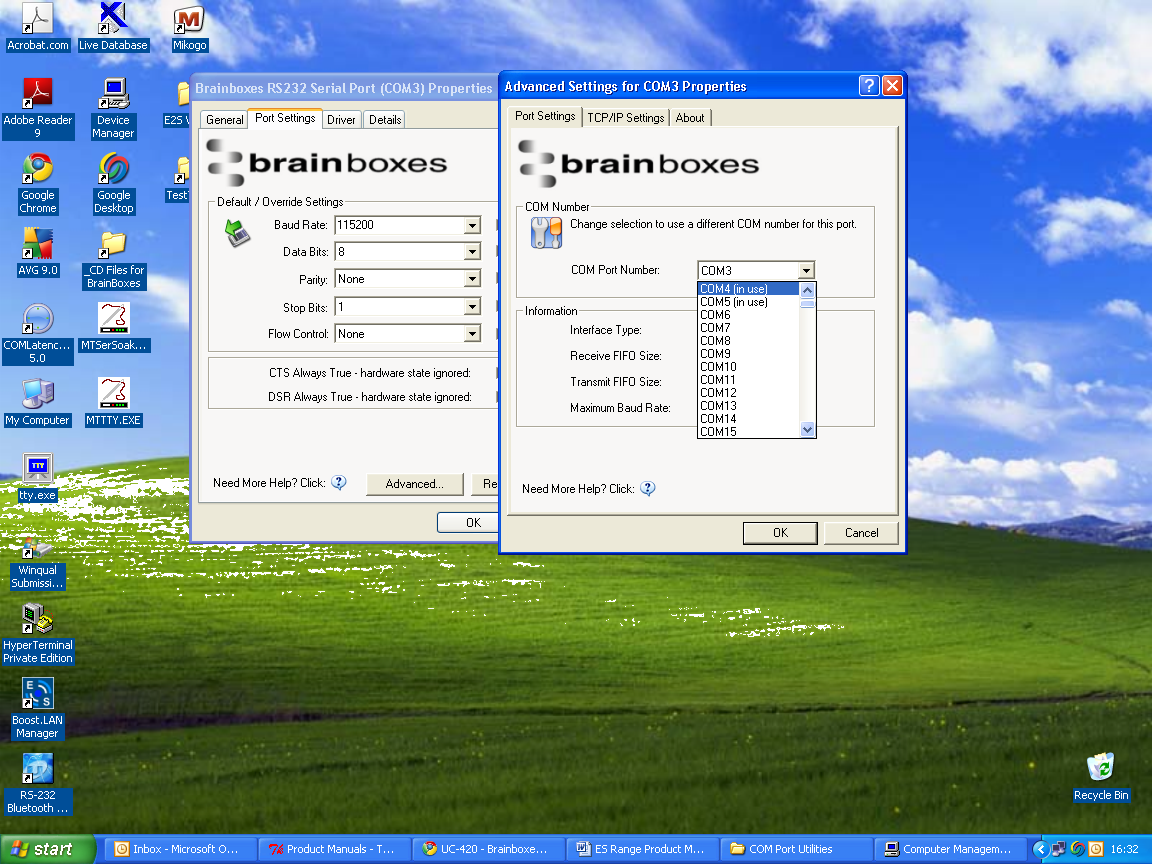
Changing your COM label
-
If you need to change the COM label, Double click on the Port entry in Boost.LAN Manager
-
Click on the 'Port Settings' tab and click Advanced
-
A new COM Port label can be selected from the dropdown menu. Click OK to set the new COM Label.
-
If the COM Port number is labelled "in use", it is either currently used by a COM Port present on the system, or is reserved for a device which is not currently present. It is possible to select this COM number and force the change, if you are sure it is not required by any other device.
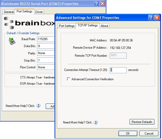
Advanced Settings - TCP/IP Settings
The TCP/IP Settings for the Brainboxes COM Port allow you to obtain the ES device's TCP/IP settings without having to go to Boost.LAN Manager or the Webpage interface. Some users may prefer this accessibility.
To open Advanced Settings, open the Port Settings (as described above) and click the Advanced button.
Select the 'TCP/IP Settings' tab.
| Setting | Description |
|---|---|
| Device MAC Address | This is assigned when the device is manufactured. |
| Remote Device IP Address | If the device is set to DHCP mode the IP address will be automatically assigned by the DHCP server. If it is set to static, this is set by the user either with the Webpage interface or using Boost.LAN Manager. This is useful for finding out the IP address of the ES device to access web page or a COM port. |
| Remote TCP Port Number | Number set by user for accessing Port on ES device. This is set to 9001 by default. |
| Connection Attempt Timeout | This is set to "0" by default. If "Connection Attempt Timeout" is other than "0", the Telnet connection to the port will be disconnected automatically (i.e. other devices can access this port) after being idle (i.e. no data is being received or sent to and from the port) for a time ranging from 1 - 20 second/s as specified. The LED for the port will go off at this point. If "Connection Attempt Timeout" setting is "0", the port will need to be disconnected manually by the user. |
| Advanced Connection Verification | This performs the following checks during the connection opening process: Verifies the port configuration is set correctly (e.g. RS-232 or RS-422/485) on the device; Verifies the device is the same device model; Forces the device to use Telnet COM port control (RFC2217). Note: By enabling this setting, it will increase the time it takes to connect to the serial port. |
The default settings have been carefully selected and should provide the right settings for the majority of users.
Alternate Access Methods
There are three methods to view and configure your Ethernet Device once it's installed on the target PC. Which method to use depends on personal preference and convenience.
Only certain settings can be configured using the Web Page Interface
| Method | Description |
|---|---|
| Boost.LAN Manager | This is the application that is installed initially to find the device and install the COM port drivers. Configuring from here is the recommended option for ease and convenience, as it centralises all Ethernet to Serial devices. |
| Windows Device Manager | This is the standard Windows Control Panel that allows users to view and control all hardware attached to a computer. The Ethernet to Serial ports can be configured from here also. |
| Web Page Interface | This allows the Ethernet to Serial device to be accessed from any PC within your network as it does not require Boost.LAN Manager. Configuration from here is recommended for socket based applications only. See the Web Page Interface section for more information. |
Proxy Server Settings
If you have a proxy server enabled on your PC this will restrict access to the web page interface. You may need to add the ES device to the Proxy Server's exceptions list. If you need help doing this contact your network administrator.
Device Swapping
In the unlikely event of a device failing, it can be easily replaced by swapping it with a device which has the same IP address. This is particularly useful when using a large number of ES devices together which have already been installed and setup and are already communicating with peripherals. The faulty device can be replaced without having to set up and install a new device. To set the device to the same IP address use the web page interface or Boost.LAN to set the IP address to the static address of the device you are replacing. For more information on IP address configuration see the IP Addressing section above.
Remote Access
The Remote access feature of the ES devices allows access to the device over the internet or from a different network. The device can be accessed either through the webpage interface, or through Boost.LAN device manager. To access the ES device remotely, you will need the IP address of the router and have port forwarding set up on your router for the device and the ports on your device. If you need assistance setting up port forwarding on your network, contact your network administrator.
Once you have the IP address and port forwarding numbers of the device and the ports, you can either access the device through the webpage or through Boost.LAN.
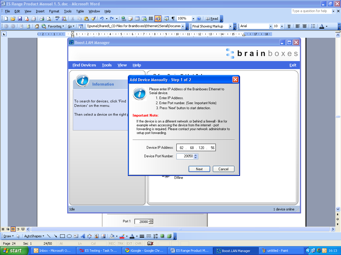
Adding a remote device using Boost.LAN Manager
-
To access the device through Boost.LAN go to Tools and then click 'Add Device Manually'.
-
Enter the public IP address of your router into the Device IP Address field, and the port forwarding number into the Device Port Number field.
-
Click the 'Next' button.
-
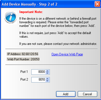
Enter the port forwarding numbers for Port 1 and Port 2 and then click the 'Add' button. The device will then appear in the Boost.LAN manager window. It can then be installed and used as if it were on a local network.
-
Enter the port forwarding numbers for Port 1 and Port 2 and then click the 'Add button
Remote Access Using Web Browser
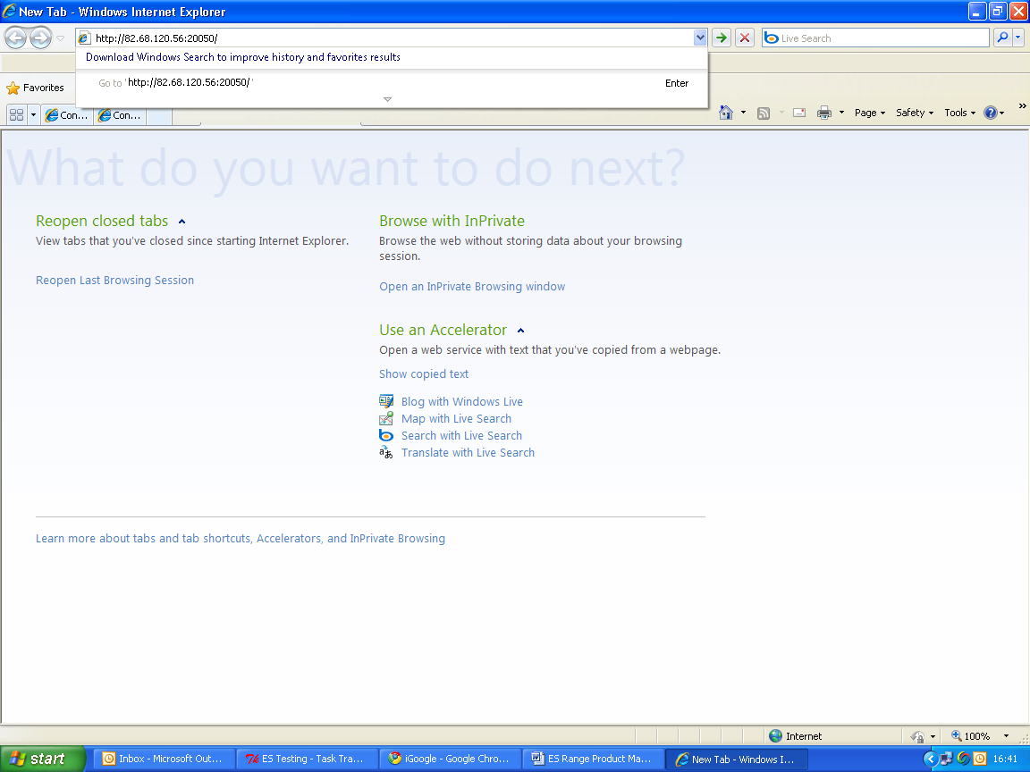
To access the ES device through the webpage you will need the IP address of your router and the ES device's port forwarding number. Type this address into the navigation bar with a colon then the port forwarding number. For example http://82.68.120.56:20050/ See the example in the screen shot below.
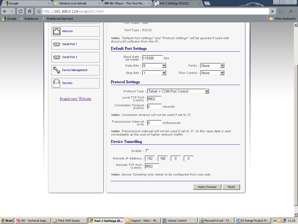
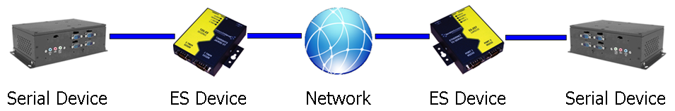
Serial Tunnelling
Brainboxes Ethernet to Serial Devices have a feature called serial tunnelling. Serial tunnelling connects two devices together to create a serial tunnel which extends the serial link over an Ethernet connection. When serial data is sent, it is converted to Ethernet packets by one Ethernet to Serial device, and then transmitted over the network, then unpacked and converted back to serial data by the other Ethernet to Serial device. An example of tunnelling is shown in the diagram below.
Serial tunnelling is set up using the webpage interface. In the following instructions there are two devices which are referred to, the local side which is the device that you are connecting from, and the remote side which is the device you are connecting to.
-
Go to the web page interface of the Local ES Device using a web browser.
-
Navigate to the page of the serial port you want to use.
-
At the bottom of this web page is the device tunnelling section.
-
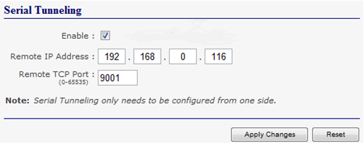
To connect tunnelling tick the enable box and select if you want the device to be master or slave. Enter the Remote IP Address and Remote TCP Port number of the ES device you want to connect to and tick the 'Enable' check box.
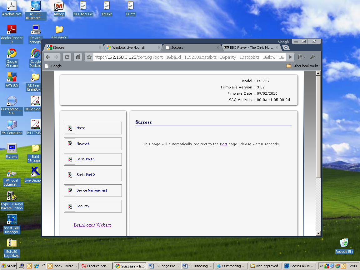
- Click the 'Apply Changes' button and you will be taken to a page which will display a success page. You will be redirected to the port page after the countdown timer has finished.
-
The devices will now be in tunnelling mode.
-
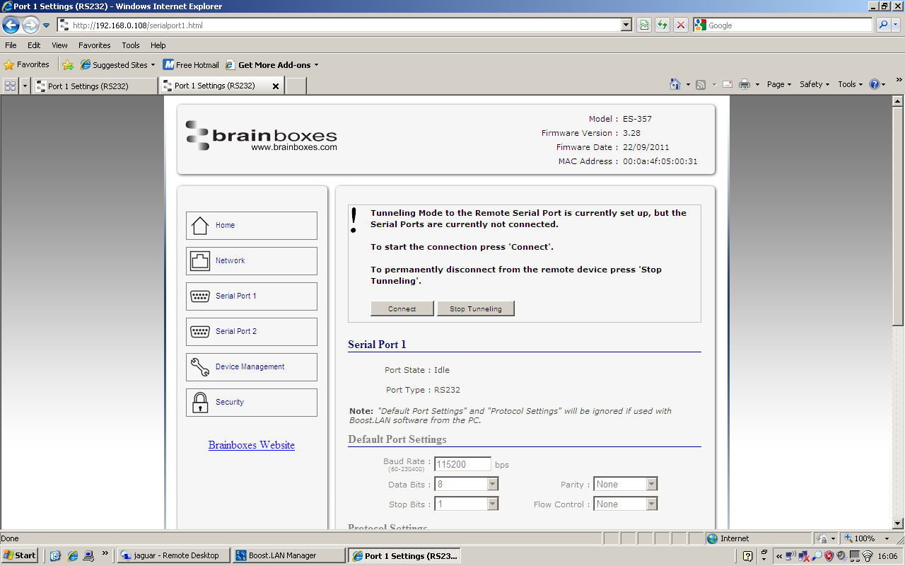
On the Local device port webpage you will see displayed the device tunnelling section with two buttons, 'Disconnect' and 'Stop Tunnelling'. By clicking the 'Stop Tunnelling' button this will disconnect the ports on the remote and local side and put both of the devices into an idle state. If the 'Disconnect' button is clicked the remote side port will be disconnected and go into the idle state, but the local side will remain in tunnelling mode.
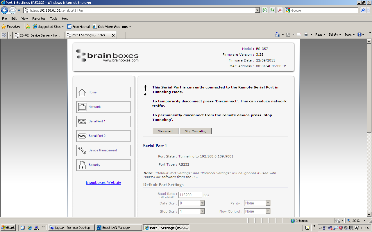
- When the remote port is disconnected the local port webpage shows a 'Connect' button. When this button is pressed the remote device will be connected to the local device and tunnelling will be connected.
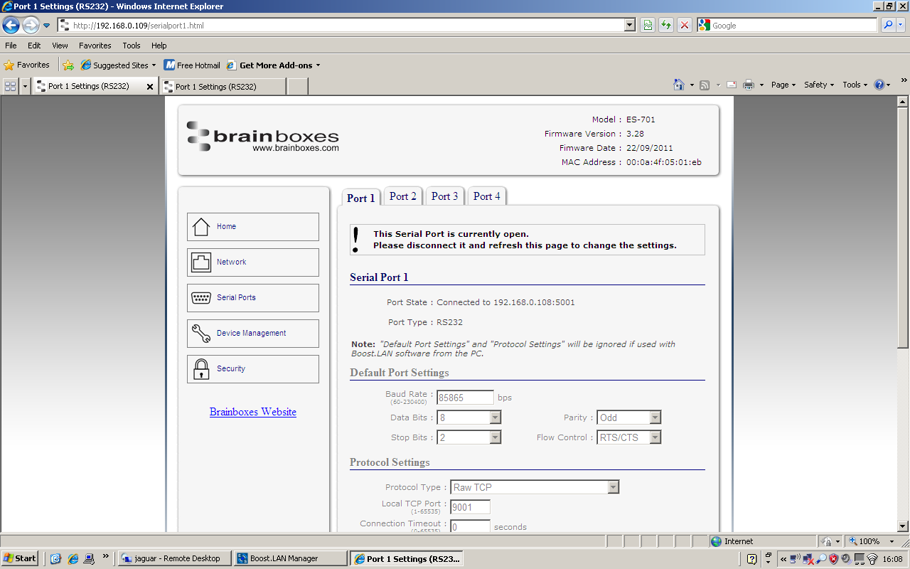
- On the remote device port webpage interface, on the Serial port that is tunnelling it will show that the port is connected.
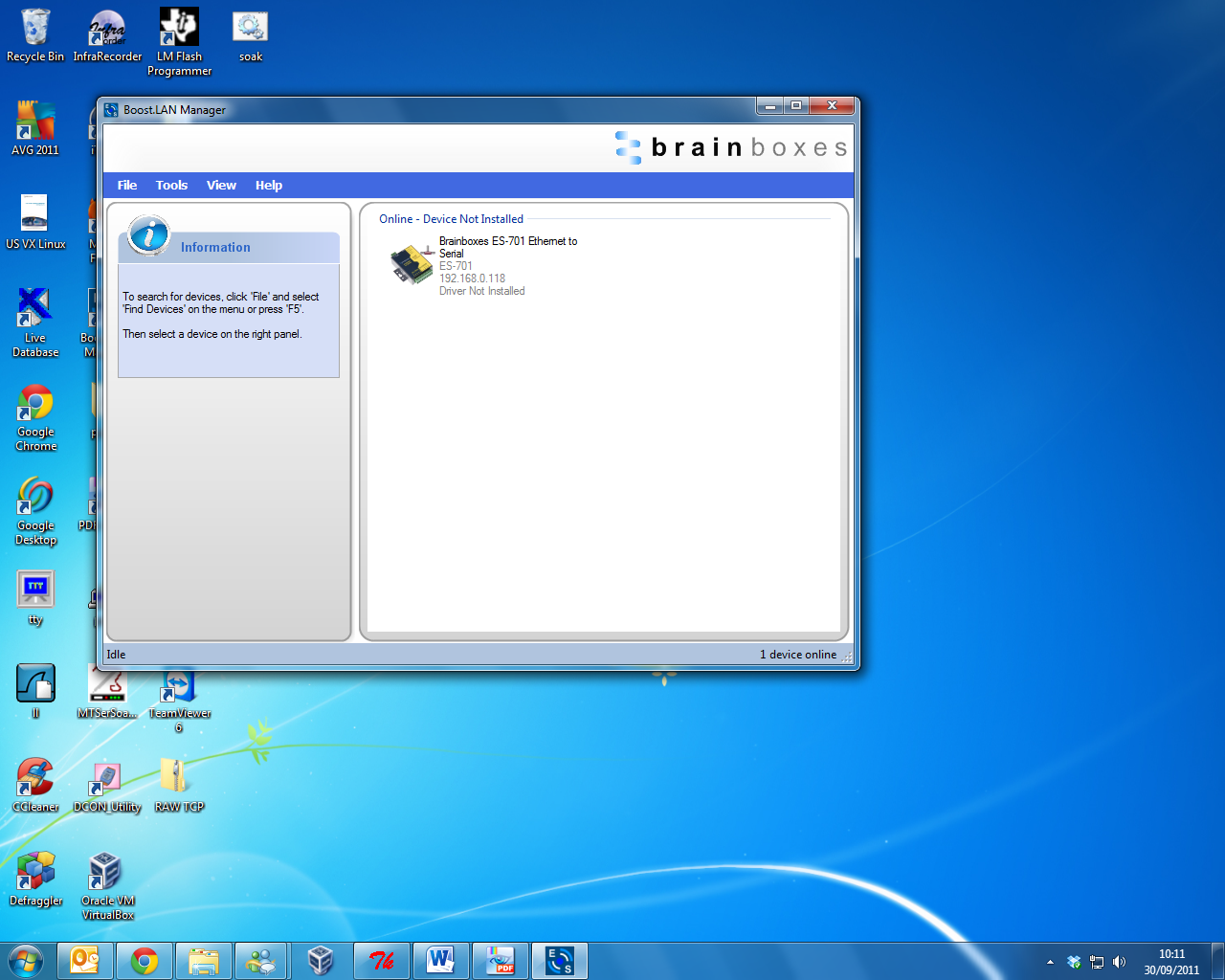
- In Boost.LAN Manager, the symbol in the image to the right will be displayed when a device in is connected in tunnelling mode.
Firewall Exceptions and Port Numbers
When using the ES devices with a firewall you may need to manually add the exception entries and port numbers to the firewall list. Listed below are the default port numbers and the firewall exceptions.
| Program Name | Default port number |
|---|---|
| Device Web Server | 80 |
| Serial Port 1 | 9001 |
| Serial Port 2 | 9002 |
| Firmware Upgrade | 67 (BOOTP Server), 68 (BOOTP Client), 69 (TFTP Port) |
Default Windows Firewall Exception entries:
- Brainboxes Boost.LAN Suite
- Brainboxes Boost.LAN Suite (Device discovery) (except Windows XP 32 & 64 bits)
- UPnP Framework (Windows XP 32 & 64 bits)
- Network Discovery (Windows 7 or later)
UPnP on/off
Turning the UPnP of your device off or on can only be done using the web page interface and will mean that the ES Device won't be broadcasting on the network. This means you won't be able to search for the device using Boost.LAN Manager. You can however add the device manually if you know the IP address and port number.
It is recommended when using Boost.LAN Manager that you install the driver before turning off the UPnP. This will ensure that when Boost.LAN is opened, the installed device will be displayed in the Boost.LAN device manager panel.
Transmission Interval
The transmission interval can be set via the web configuration page. The factory default for the Transmission Interval is set to 0. With the transmission interval set to 0 milliseconds, the incoming data is transmitted straight away, in small bytes which cause a lot of network traffic and high CPU usage on the PC receiving the data.
When there is a transmission interval set, there is a delay on sending the data. The first byte of data that comes in is sent immediately but after this no further data is sent until the transmission interval time has passed. The ES device then accumulates any further bytes of data and then sends them all together in one large chunk after the transmission interval, reducing network traffic and CPU usage.