
ED Web Configuration Pages
Introduction
The web configuration pages for the ED device allow you to configure all the settings on the device and view the status of the device. To access the web configuration pages, type the IP address of the device into a web browser.
We recommend that you use Internet Explorer Version 7 and above, or any modern web browser.
In the top right corner of every page there will be a box that displays information about your device including the model, firmware version, MAC address and uptime.
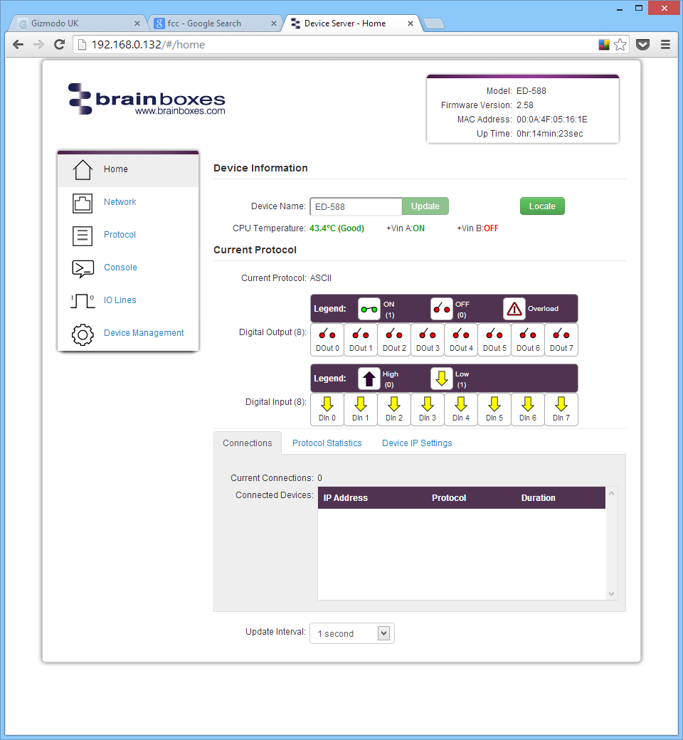
Home Page
The Home page is the default page that loads when you enter the IP address of the device into a web browser. This page displays device information and a visual display of the states of the input and output/relay lines.
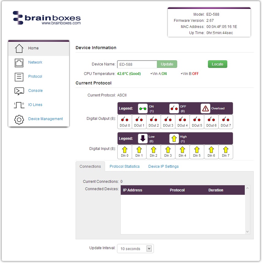
Device Information
The Device Information section shows a text box with the current device name. This is the name used to identify the device on your network. By default, the device name is set to the product name but can be changed.
Locate Button: When pressed, all the LEDs on the front of the device will start flashing for 10 seconds. This helps identify which device you are configuring when multiple devices are installed on a DIN rail.
The section also displays:
- CPU temperature (green = normal, red = overheating)
- Power supply voltages (Vin A and Vin B states)
Current Protocol
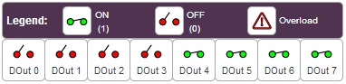
The Current Protocol section displays the state of the digital inputs and outputs:
- Digital Inputs: Three states - on, off, or overload
- Digital Outputs: Two states - high or low
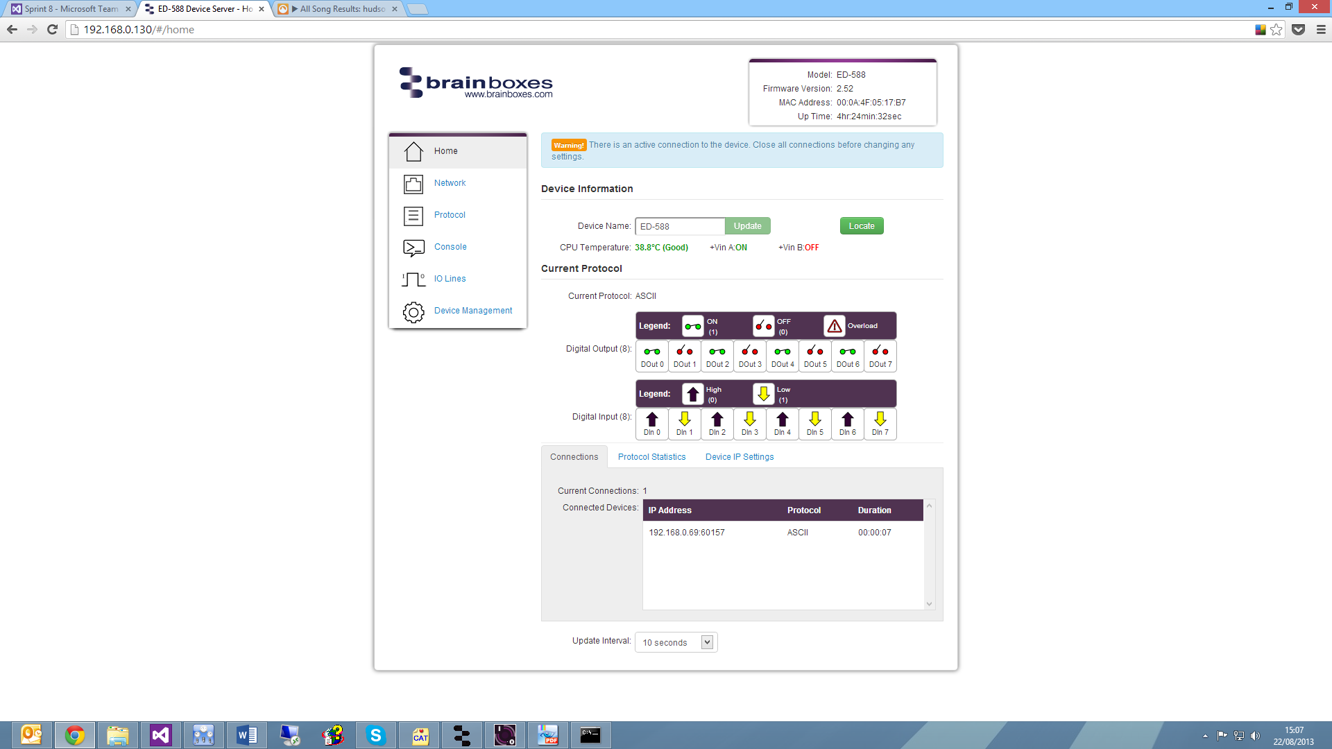
Connections
The Connections tab displays information about active connections to the device, including the number of current connections and details about any devices connecting to the ED device.
When a connection is made, there will be a warning at the top of every page. Some settings require the device to be restarted, and the ED device cannot be restarted while a connection is being made to it.
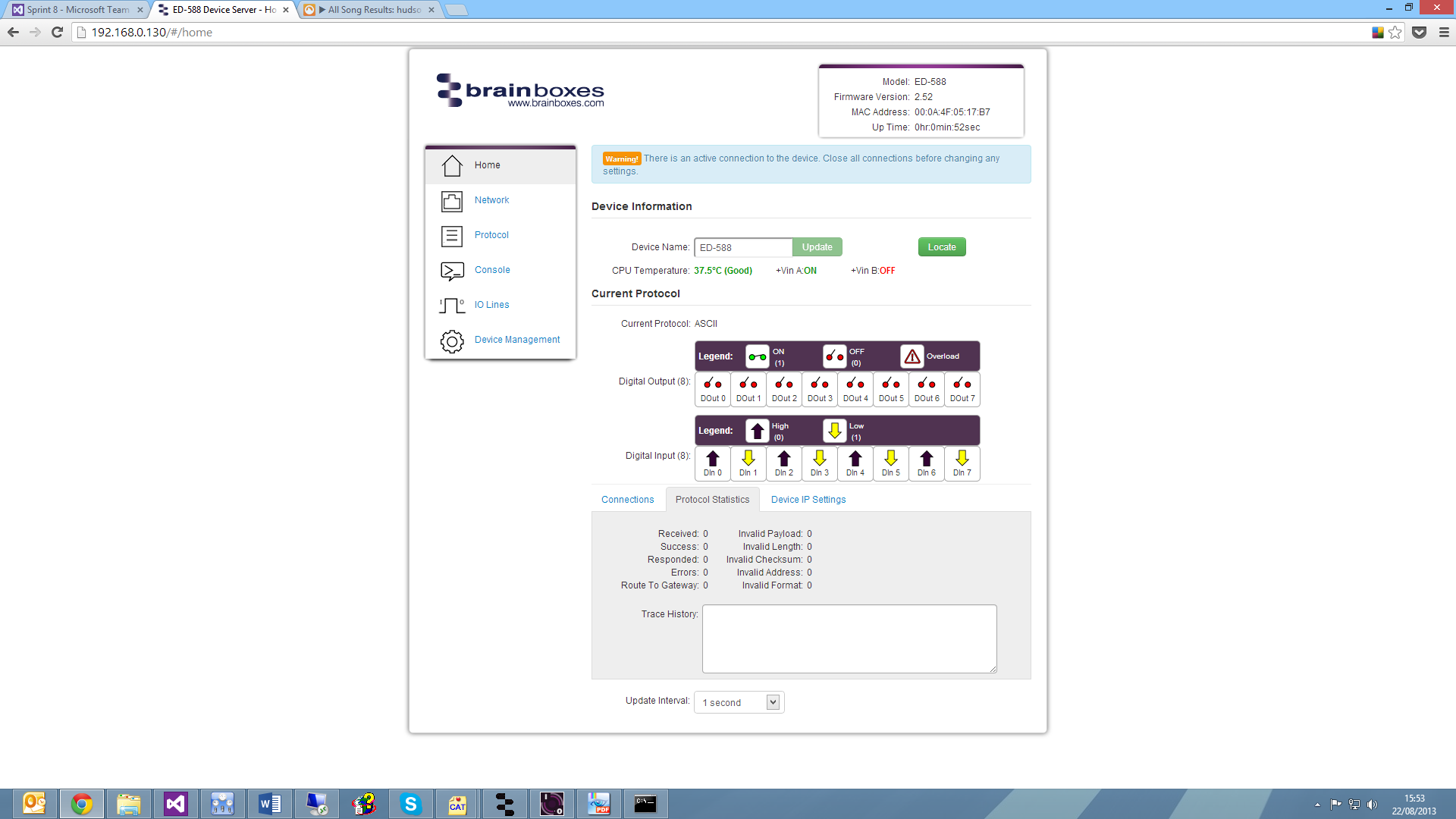
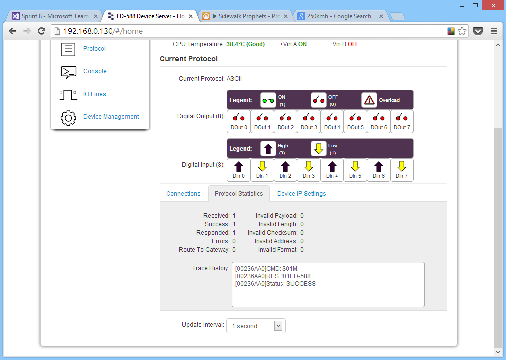
Protocol Statistics
The Protocol Statistics tab displays information about protocol commands sent to the device since it was powered on, including a history of all commands and responses.
Device IP Settings
The Device IP Settings tab shows the device's network settings. These can be changed on the Network page.
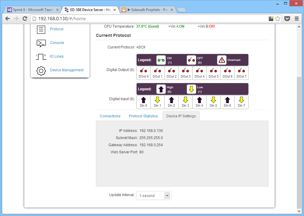
Update Interval
The Update Interval dropdown controls how often the device information refreshes automatically:
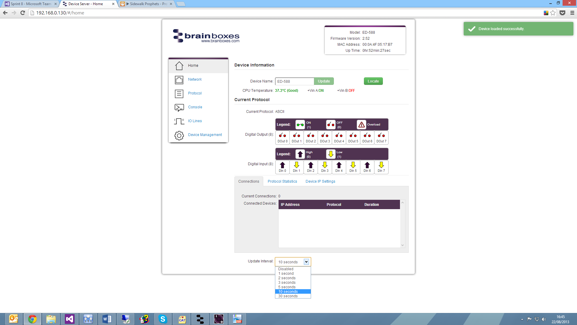
- Set to a time interval (e.g., 5 seconds) for automatic updates
- Set to 'Disabled' to refresh manually
Network Page
The Network page allows you to configure all network settings of the ED device.
Network IP Address
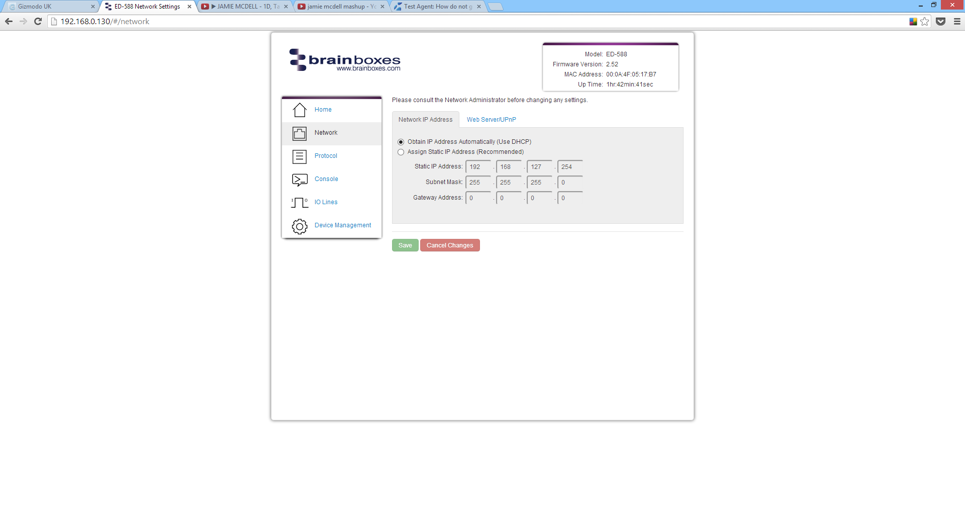
Options:
- DHCP: Obtain an IP address automatically
- Static IP: Specify a fixed IP address
By default, the ED device uses DHCP. If no DHCP server is present, after 60 seconds the device will switch to a static IP address of 192.168.127.254.
Web Server/UPnP
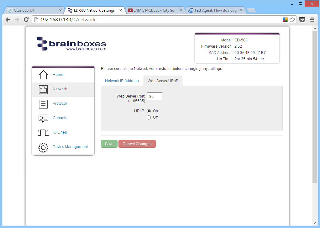
Configure:
- Web Server Port number (default: 80)
- UPnP on/off setting
Serial Port Page
The serial port page (available on some models) allows you to configure serial port settings.
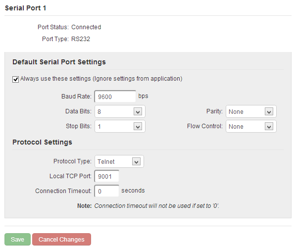
Always Use These Settings
If ticked, the serial port will communicate using the configured baud rate, data bits, parity, stop bits and flow control regardless of what settings the application is using. This is useful for interfacing to equipment which uses unusual baud rates that your application does not support.
Protocol Type
| Protocol | Description |
|---|---|
| RAW TCP | Data sent over the network is the same as data sent over the serial link. Configuration via web page only. |
| Telnet | Based on RFC2217 standard. Allows dynamic serial port configuration. Data is encapsulated over serial link. |
If you are using the Brainboxes Windows driver to create a COM port, the driver will use Telnet regardless of the protocol setting on the webpage.
Local TCP Port
Configures which TCP port the serial port of the ED device will use.
Connection Timeout
- Default: 0 - The port will never be disconnected automatically
- Other values - Connection will be disconnected after being idle for the specified time
Protocol Page
The protocol page has all ASCII and serial gateway settings.
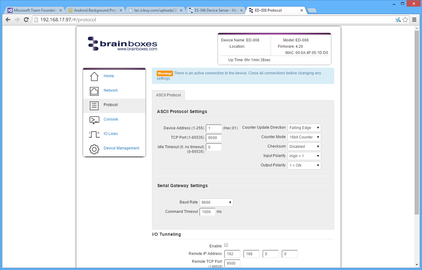
ASCII Protocol Settings
Device Address
A hexadecimal value (1-255) specifying the target device for ASCII commands.
TCP Port
The network port used to connect to the device. Default: 9500
Idle Timeout
If no communication occurs for the specified time, the connection will be closed. Default: 0 (never close automatically)
Counter Update Direction

| Setting | Description |
|---|---|
| Falling Edge | Counter increments when signal goes from high to low (default) |
| Rising Edge | Counter increments when signal goes from low to high |
Counter Mode
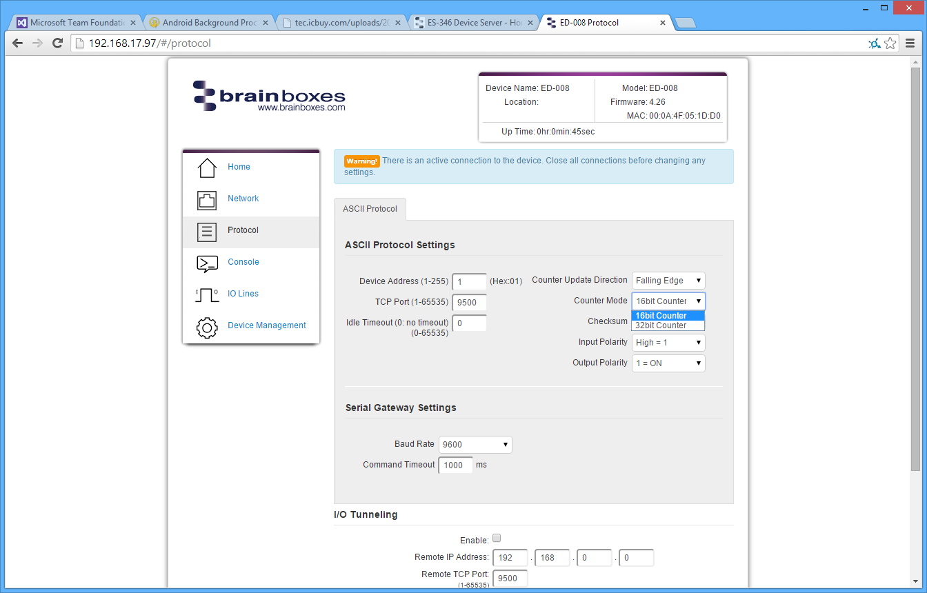
| Mode | Range |
|---|---|
| 16-bit Counter | 0 to 65535 |
| 32-bit Counter | 0 to 4294967295 |
Checksum

When enabled, all commands and responses must contain a valid checksum otherwise the data is discarded. Default: Disabled
Input Polarity

| Setting | High Voltage | No Voltage |
|---|---|---|
| High = 1 (default) | Displays as 1 | Displays as 0 |
| Low = 1 | Displays as 0 | Displays as 1 |
Output Polarity
![]()
| Setting | Description |
|---|---|
| 1 = ON (default) | Voltage on line = 1, No voltage = 0 |
| 0 = ON | Voltage on line = 0, No voltage = 1 |
Serial Gateway
The Serial Gateway feature (available on ED-5XX models) turns the ED device into a serial gateway which allows it to send commands out the gateway port to another ASCII protocol compatible device such as NuDAM, eDAM and ADAM modules.
Specifications:
- Half duplex RS485
- 8 data bits, no parity, 1 stop bit
Baud Rate
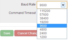
Default: 9600
Command Timeout
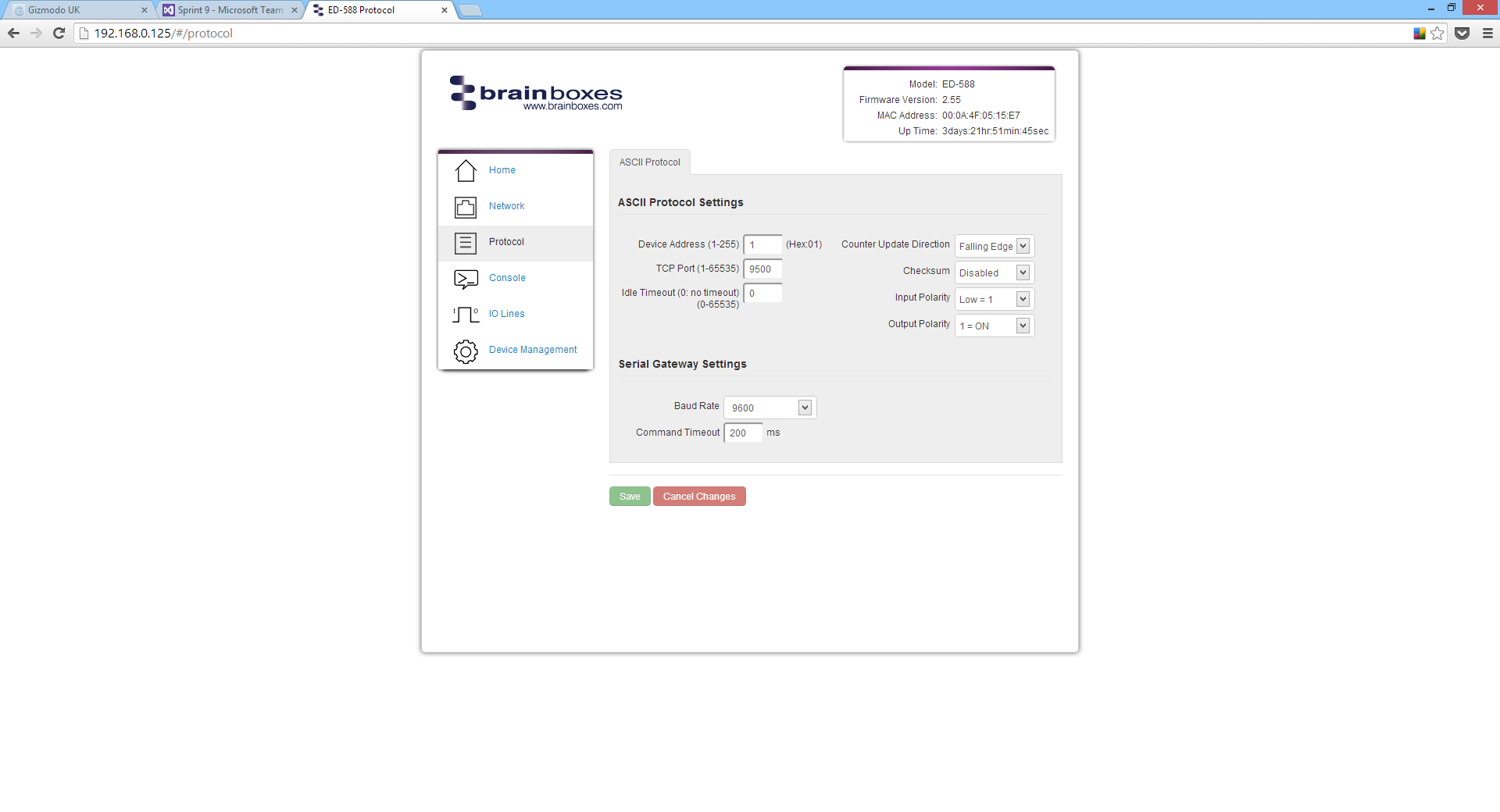
Determines how long the ED device will wait for a response from the Serial Gateway. Default: 200 milliseconds
Console Page
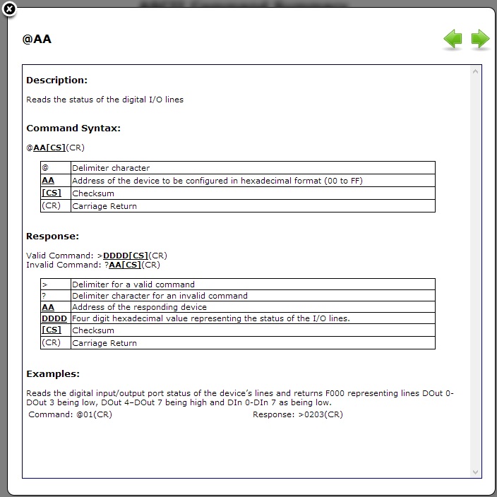
The Console Page contains a console window for sending ASCII commands directly to the device.
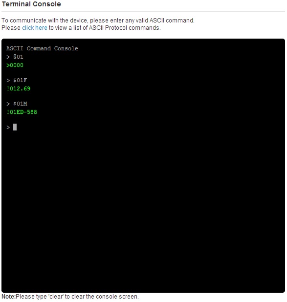
Commands are entered in the console and responses are displayed in green. This is the simplest way to send ASCII commands to the ED device.
A link to the ASCII protocol command reference is also available:
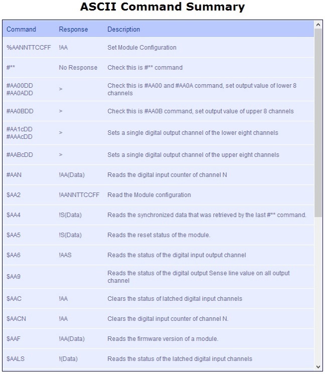
IO Lines Page
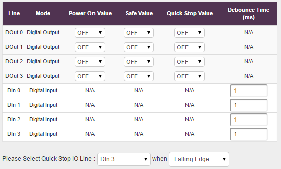
The IO Lines page allows you to configure Power-On Value, Safe Value and Quick Stop Value for each output line.
The Quick Stop feature has not been designed or qualified as an Emergency Stop device and must not be used as part of a safety critical control system.
Power-On Value
Determines what state the output lines will go to every time the device is powered on. Default: All outputs set low
Example output state after power on:

Safe Value
The state that output lines will go to when the device enters a Watchdog state. This ensures outputs always revert to a safe, known state even if communication problems occur.
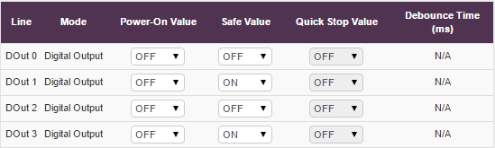
When in Watchdog state, a warning message appears:

And outputs are set to the configured safe state:
Quick Stop Value
When enabled, all output lines will go to a user-specified state when a preconfigured input transitions to high or low.
Configuration:
- Select the input line to monitor:

- Select the trigger condition:

- Set the digital output pattern for when triggered
Debounce Time
Debouncing ensures that only a single signal is acted upon for a single opening or closing of a contact.
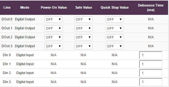
The debounce time (in milliseconds) ensures that only one digital signal can be registered within a given time period.
Device Management Page
The Device Management page has two options:
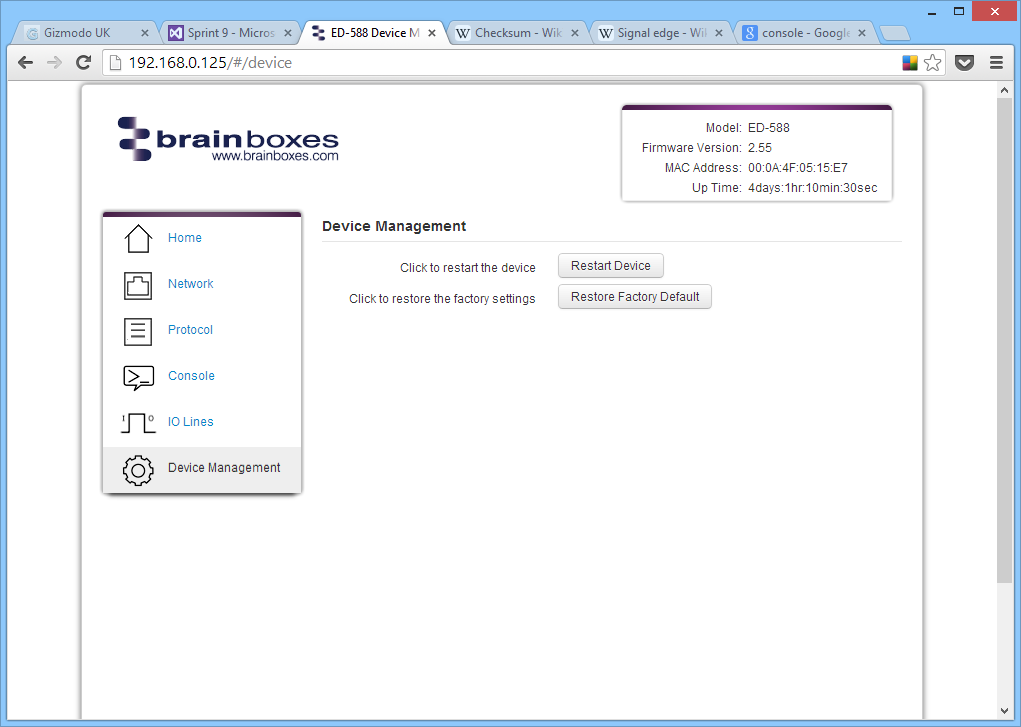
Restart Device
Clicking 'Restart Device' will power cycle the device.
There must be no active connections to the device. If a connection exists, a warning message will be displayed.
Restore Factory Default
Clicking 'Restore Factory Default' will revert all settings to their factory default values.
Factory Default Settings
| Category | Setting | Default Value |
|---|---|---|
| Network Settings | Network IP Address | DHCP Mode |
| Web Server Port | 80 | |
| ASCII Protocol Settings | Device Address | 01 |
| TCP Port | 9500 | |
| Idle Timeout | 0 | |
| Counter Update Direction | Falling Edge | |
| Checksum | Disabled | |
| Input Polarity | High = 1 | |
| Output Polarity | 1 = ON | |
| Serial Gateway Settings | Baud Rate | 9600 |
| Command Timeout | 200 ms |