PE-505/508 Troubleshooting
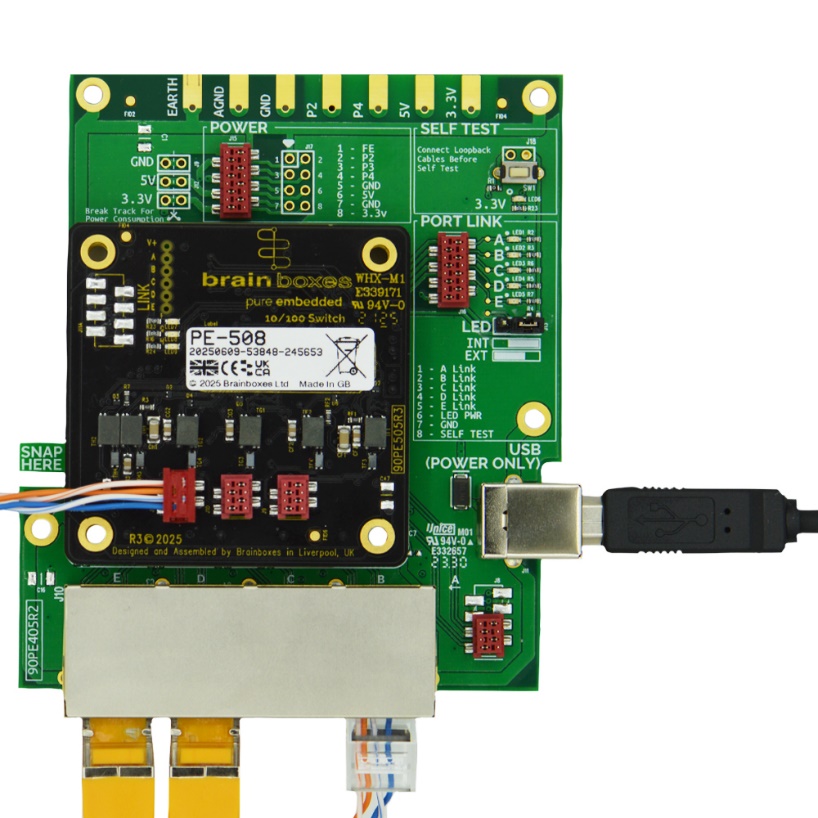
Device Markings

Markings on the rear of this device are subject to change. This will not affect the functionality of the device.
| Reference | Description |
|---|---|
| A | Debug Header (See Self-Test Procedure below) |
| B | LED Status Indicators |
| C | 90PE505R2 ← PCB Revision |
| D | GND Mounting Hole |
| E | Product Variant, Serial Number and Date of Manufacture |
| F | FE Mounting Holes |
| G | [PE-508 Only] — 3 x MicroMatch RJ45 Ports & Magnetics |
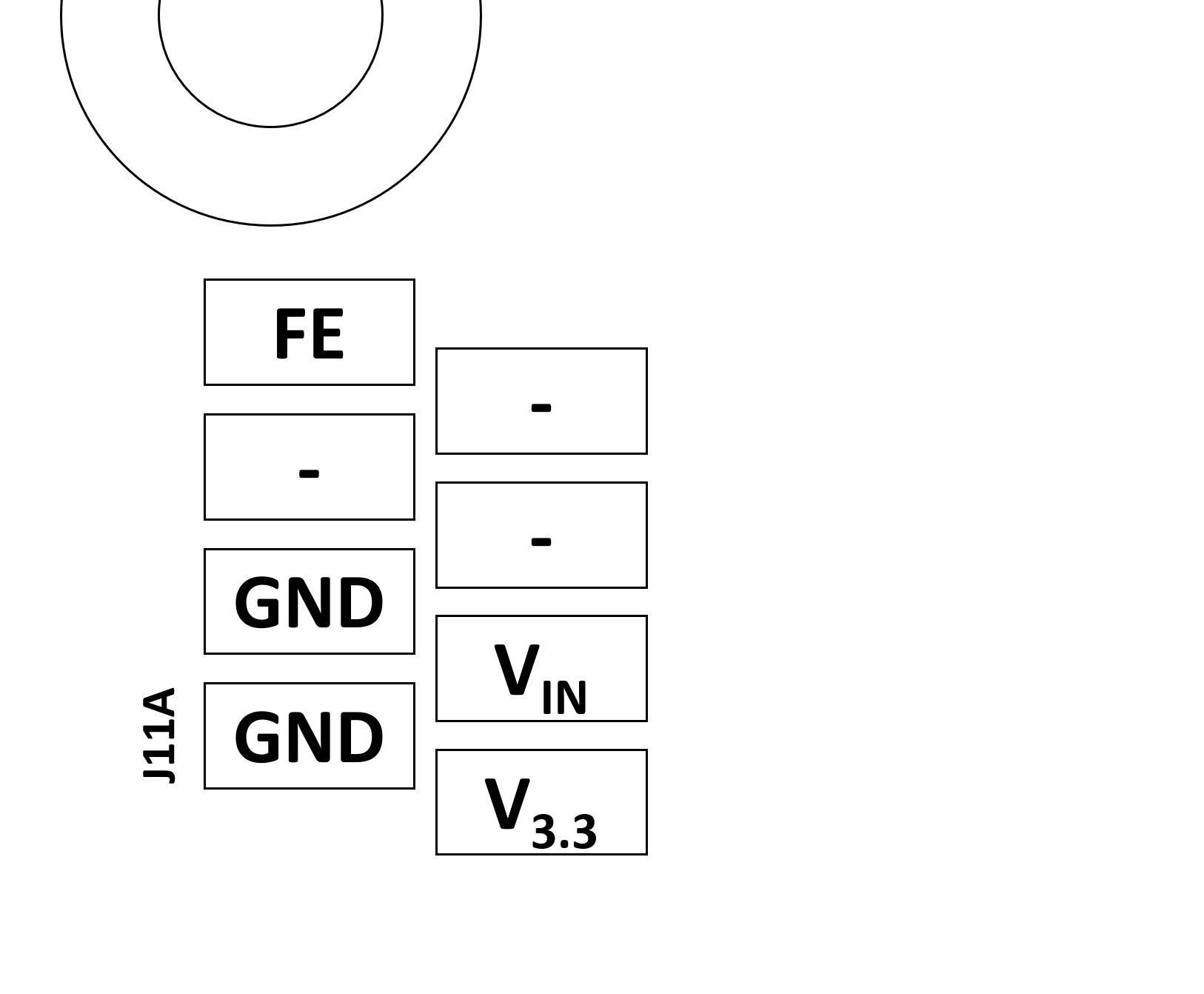
Power Supply Verification
There are several pads on the reverse of the board that can be used to diagnose issues with power delivery. The voltage on pads V_in and V_3.3 must be within the tolerances defined in the Specifications section. If the measured values exceed those listed, correct operation is no longer guaranteed.

Self-Test Procedure
Check the Device Markings section above to determine device revision. If your revision is not included here, check the Brainboxes website for the updated datasheet.
90PE505R2, 90PE505R3
The PE-505 and PE-508 implement a self-test facility to ensure that each port is operating correctly. Each port should be looped back by connecting RX+ to TX+ and RX− to TX− for testing. We recommend using a PE-405 Eval Kit for this purpose:
- Connect 2 ports directly together using a suitable cable or connect Pin 1 to Pin 3 and Pin 2 to Pin 4 for each of the ports (RX+ to TX+ and RX- to TX-)
- Connect a push button between Pin 6 and Pin 8 of the LINK status connector
- Power the device on
- Press the test button
- Wait 5 seconds and press the test button again
- Ports which pass the Loopback test should Light their link LED
- Ensure any loopbacks are removed prior to reconnecting the switch to your network to avoid network issues